This is a recipe for reducing medium deep (~15 minute integration with more than 10 exposures), blank field IRAC survey data in all four bands, similar to the SCOSMOS Legacy Science Program survey (http://irsa.ipac.caltech.edu/data/SPITZER/docs/spitzermission/observingprograms/legacy/). In this recipe, we outline the steps needed to use MOPEX to produce science grade images from IRAC basic calibrated data (BCD). We focus on the detailed set-up for channel 1, and then outline what settings need to be changed for the other three IRAC channels.
Background subtraction for this type of data and object density is optimally treated with the default "Overlap" pipeline. Outlier rejection is best treated with a box outlier and temporal outlier rejection. The more involved "Dual Outlier" method is not needed with this level of coverage. Images are interpolated onto a final grid of 0.6" per pixel using the "Drizzle" algorithm. This optimally samples the PSF by taking advantage of sub-pixel offsets in the data.
There are additional recipes in this cookbook for other types of IRAC data, including deeper and shallower blank field data. You should compare the settings to select those optimal for reducing your data. However, this recipe is the most detailed, and should be read first before moving on to the others.
If your data have been processed by version S18.0 or later of the IRAC pipeline, you do not need to run the pre-processing steps because corrected BCD (CBCD) data will be provided. However, if you do need to run the pre-processing, IDL version 6.2 or newer and the IDL Astronomy Users's Library (http://idlastro.gsfc.nasa.gov/) are required.
3.2 Organizing Files and Directories
Before starting with this recipe, you should download the example data set using the Spitzer archive interface. The COSMOS IRAC AORs used in this recipe are 15536640, 15537152, 15540224, 15540736, 15541504, 15546112, 15546368, 15547392, 15547904, 15552512, and 15553024. These total ~6GB of data for all four channels. Specify that you need the Basic Calibrated Data (BCD) and the corrected BCD (CBCD) for all four IRAC bands. The BCDs are single images which have been run through the Spitzer online calibration pipeline and have had some basic artifact clean-ups applied (orientation flipping, dark subtraction, flat field correction, conversion into units of MJy/sr).
You likely have several AORs, so multiple directories will be created, each with a subdirectory labeled ch1/, ch2/, ch3/, and ch4/. Under each of the channel directories you will find a bcd/ directory containing the calibrated data. We strongly encourage you to download the latest processing of data from the Spitzer Heritage Archive instead of using earlier processings.
You need to make several lists of input files for MOPEX. A separate list should be made for each IRAC channel. The only required list contains the input images (_bcd.fits or _cbcd.fits files). However, a list of the uncertainty maps (_bunc.fits or (_cbunc.fits files) and a list of the bad pixel masks (_bimsk.fits files) is strongly recommended if you wish to remove artifacts. Give the following command in the directory under which you have downloaded the data from the 11 AORs mentioned above:
You need to edit the lists to remove all short frames, i.e., frames with "0000_0000" and "0000_0001" in their file names. E.g., the following command should work:
sed �e �/0000[_]0000/ {d; b} /0001[_]0000/d� ch1_bcd.lst > ch1_bcd.list
The MOPEX tool processes calibrated imaging data (BCDs and CBCDs) into a science grade mosaic and can produce a photometric catalog. MOPEX includes modules that match the background, astrometrically register and re-sample the images, remove outliers, combine the individual data into a final mosaic, and measure photometry. MOPEX can be run on the command line or with a graphical interface (GUI). This recipe is written for the GUI interface, but the provided setup files can be used with the command line version of MOPEX.
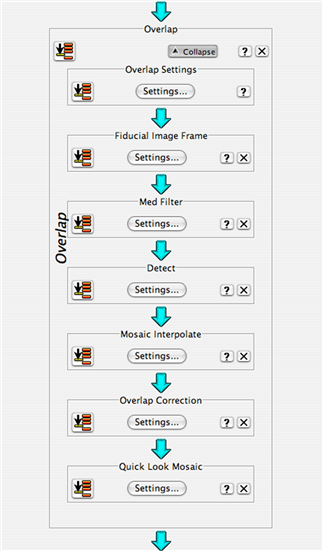
MOPEX has several major components that can operate together as one pipeline or separately on different sets of data. The major components are "Overlap", "Mosaic", "APEX multi-frame", and "APEX single frame". Overlap is designed to remove image background variations due to foreground light sources. Mosaic removes defects and spurious pixels (e.g. cosmic rays), reassembles the data onto a common pixel grid, and combines your data into a science grade mosaic with a corresponding noise map. The two APEX modules find objects and measure photometry on the final calibrated data. APEX multi-frame measures photometry on each frame individually, while APEX single frame measures it on the combined mosaic.
This recipe will detail the set-up of a pipeline and explain the various parameter choices. All of the settings and how to change them will be explained in detail for IRAC Channel 1 (ch1). After the channel 1 example, the setting changes required for the other three channels will be explained.
Note that when a sub-menu (including the help menu, but not including the component menu) is open in the MOPEX GUI, all other windows are frozen. If you can not modify a setting or scroll through the help menu, check for other open windows. This is a feature of JAVA and can not be easily corrected.
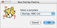
To begin, start the MOPEX GUI and select "New Overlap Pipeline" from the file menu. This will bring up a dialog box asking which template you would like to use:
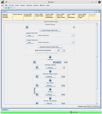
Select "Overlap, IRAC ch1", and click OK. This will bring up a window with the default IRAC ch1 overlap pipeline and a second window listing the modules you can add to the overlap workflow.
The GUI is laid out as a data flow diagram. The first box specifies the input data and each subsequent box represents a module in the data reduction pipeline. Each module acts on the data from the previous module and then passes the data to the next module in the order specified by the GUI window. When you add a module it will be placed in the appropriate position in the work flow. If the module you added depends on previous modules, you will be informed which modules you need to add.
You can insert other components to the pipeline by clicking on the buttons along the top of the window. When you insert other components, additional windows will open, listing modules in each component�s workflow. When you want to run the pipeline you can click on the green play button at the top of the window.
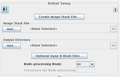
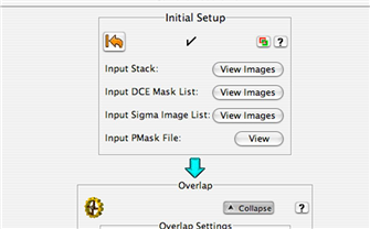
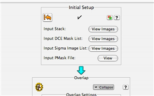
3.4 Initial Setup
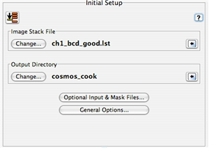
The first step is to specify which data you want reduced and what you want the final image to look like. In the initial setup box, specify which file lists MOPEX should use for the stacking. The first dialog box should look like this:
Click "Add..." under "Image Stack File" and select the file containing the list of IRAC Channel 1 image files you created earlier.
Click "Add..." under "Output Directory" and specify where the intermediate and final data products should be saved.
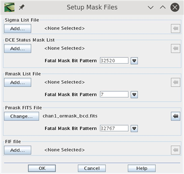
Next, click "Optional Input & Mask Files...." which will open this dialog box:
In this dialog box you specify the input uncertainty and mask files, along with which flags will be used to reject pixels (the Fatal Mask Bit Patterns). The complete list of bad pixel flags can be found in the IRAC Instrument Handbook section 7.1.1. Clicking on the downward facing arrow to the right of each "Mask Bit Pattern" window will open a window which allows you to turn each bit on or off.
Click "Add..." under "Sigma List File" and specify the list of cbunc files created earlier.
Click "Add..." under "DCE Status Mask List" and specify the list of bad pixel (bimsk) files created earlier.
Use the default Fatal Mask Bit Pattern 32520 (bits 3, 8-14).
Rmasks contain a list of pixels rejected by previous runs of MOPEX. In version 16.3.7 and later of MOPEX there is no need for an input list in most cases. In previous versions a list was needed in the second pass reduction if you were using Drizzle.
Even if you are not providing a list of rmasks you need to set the "Fatal Mask Bit Pattern" for later in the pipeline. For this type of data set the Rmask Fatal Bit Pattern to 10 (use box and temporal outlier) rather than the default 7 (use dual outlier).
Click "Add..." under "Pmask FITS File" and specify the bad pixel mask you downloaded. For the COSMOS Cycle-2 data the file is "dec05_ch1_bcd_pmask.fits". The default "Fatal Mask Bit Pattern" of 32767 is appropriate.
The FIF file records the "Fiducial Image Frame". This file will contain WCS information that allows you to match various sets of Spitzer data to one another and specify the image frame for other channels. Leave this as the default unless you have a FIF you want matched. See the Helpdesk Knowledgebase for more information about changing the FIF ("How do I modify my FIF.tbl so that MOPEX makes my output mosaic the size of my choice?").
Once you are finished specifying the input parameters click "OK" to return to the pipeline view.
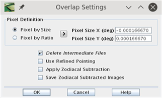
In the pipeline view click on ��Settings" under ��Overlap Settings". That will bring you to this window:
where you can specify the output pixel size. A scale of 0.6 arcseconds per pixel has been found to be optimal. That corresponds to an X pixel size of -0.000166670 and a Y pixel size of 0.000166670. Setting the X pixel size to a negative value will generate an image with RA running to the East, which is the default for most FITS images.
Click OK when you have specified the pixel size to return to the pipeline view.
3.5 Channel 1 Overlap
The Overlap module corrects for variable background levels in your data by adding a constant value to every frame. As the name suggests, the additive offset is determined by measuring the background level in overlapping frames. This requires generating a first pass mosaic and masking objects which may contribute to the background. The default settings are optimal. However, if you have very extended objects, a crowded field, or extended emission in your field you may want to adjust some parameters.
Below is an example of the default Overlap pipeline:
3.5.1 Overlap Settings
This configures the basic settings for the overlap module. To configure it click on "Settings..." in the "Overlap Settings" box.
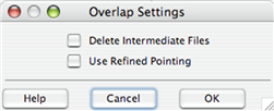
You may wish to check the "Delete Intermediate Files" box if you are short on disk space. This will remove the intermediate data products when they are no longer needed.
Check "Use Refined Pointing" to use pointing updates if you have applied them to the BCD files. This is generally not required for data taken after GO proposal Cycle 2. The pointing refinement involves identifying point sources in the IRAC frames and correlating them with 2MASS source positions. The pointing refinement typically improves the positional error to less than 0.3 arcseconds and removes any systematic offsets. For more information, see Section 5.3.1 of the IRAC Instrument Handbook.
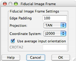
3.5.2 Fiducial Image Frame
The "Fiducial Image Frame" sets the parameters for the overlap mosaic. These are distinct from the final data mosaic. There is no reason to change these settings since this mosaic is only intended for a quick look.
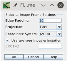
To configure it, click on "Settings..." in the "Fiducial Image Frame" box. This will bring up the following dialog box:
Edge padding specifies the number of blank pixels around the edge of the data. A blank area of this width will be placed on all sides of your final mosaic. The default value of 10 is fine for most cases.
Projection specifies the WCS projection. The default "TAN" is used for most astronomical FITS images. Coordinate System specifies the celestial system for the WCS. Options are J2000, Galactic or Ecliptic. For extragalactic studies J2000 is the appropriate setting.
The "Use average input orientation box" specifies how the WCS rotation is specified. Leaving this box checked will minimize the size of the final fits image by making the final mosaic as rectangular as possible. However, it is often desirable to specify a fixed rotation to match other data. For COSMOS, un-check this box and set CROTA2 to 0.00.
When you are finished, click "OK".
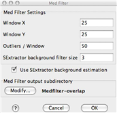
3.5.3 Med Filter
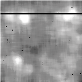
This module filters and removes the background in individual images. It is needed by the "Detect" module to find objects. Med filter constructs a background by measuring a clipped median in a window around each pixel and subtracting it. If you have very extended sources or a crowded field, you may want to increase the size of the window and/or increase the number of pixels rejected in each window.
An example image and the background determined by "Med Filter" is shown below.
Note the background around bright extended objects is too high. However this is not important as long as the majority of real objects are found and masked in the next step.
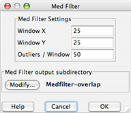
You can control the window size and clipping by clicking on "Settings...", which will bring up this window:
Window X and window Y set the x and y size of the median window. However, this step is computationally intensive and the required time scales geometrically. So increasing the window size by a factor of two will increase the required compute time four fold.
Outliers/Window specifies how may outlier pixels will be removed before calculating the median.
The "Med Filter output subdirectory" specifies where the resulting images will be stored for you to inspect.
In MOPEX 18.2.0, an additional option was added "Use SExtractor background estimation":
Turning on this flag improves the pipeline speed by about a factor of 2 without affecting the results in any significant way.
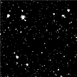
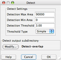
3.5.4 Detect
This module detects objects so they can be masked when determining the background in overlapping regions. If you have very extended sources or a crowded field you may want to modify the detection settings to optimally mask the objects.
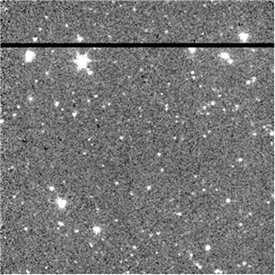
A detection map from the overlap "Detect" module and a raw image with objects masked is shown below.
One could try to improve the masking by setting the "Detection Threshold" lower. However, as long as the overlap between frames is large and the majority of objects are masked, this is unnecessary.
To configure this module, click on "Settings..." in the "Detect" box.
The detection area settings control the maximum and minimum size of an object considered to be real.
The detection threshold is the minimum S/N of the object peak. The noise is determined by the uncertainty maps from the BCD pipeline unless you add a S/N estimator to the pipeline. You should only do that if you feel the provided uncertainty maps are wrong for some reason.
The "Detect output subdirectory" will contain the output object mask for your inspection.
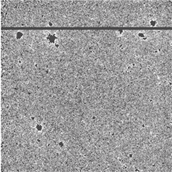
3.5.5 Mosaic Interpolation
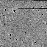
The "Mosaic Interpolate" module does the first pass interpolation of the data onto the FIF. For overlap, this is intended to be a quick look which simply matches the frames to one another so the relative backgrounds can be determined. Therefore, the fastest interpolation, "Grid" (nearest neighbor), is used. If you want to use the quick look mosaic for something you may want to use a better, but slower interpolation than grid. An interpolated image is shown below.
Note the field geometry has changed slightly and there is slight aliasing across the image. The aliasing is due to the fast "Grid" interpolation.
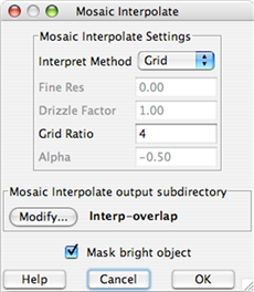
To configure this module, click on "Settings..." in the "Mosaic Interpolate" box.
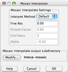
The "Interpret Method" menu sets the interpolation method.
Grid Ratio specifies how fine of a sub-pixel grid will be used for the interpolation.
The "Mosaic Interpolate output subdirectory" specifies the location of temporary files.
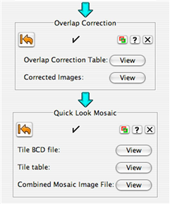
3.5.6 Overlap Correction
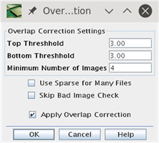
This module calculates and applies a correction which produces a consistent background across your image. If you are having problems matching the background you may want to adjust the outlier rejection in this module by clicking on "Settings...".
The "Top Threshold" and "Bottom Threshold" and "Minimum Number of Images" settings are used to control outlier rejection. If a frame is "Top Threshold" sigma above or "Bottom Threshold" sigma below the median correction at this position in the mosaic it will be rejected. The "Minimum Number of Images" setting specifies the minimum number of overlapping images at a given position required to do outlier rejection.
If the "Apply Overlap Correction" box is not checked, the determined background corrections will not be applied. They will still be recorded in a table file.
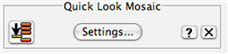
3.5.7 Quick Look Mosaic
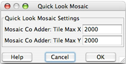
Note that this module has to be manually added to the flow. This module generates a quick look mosaic with no outlier rejection. This is useful to determine if the background has been properly subtracted. If you already know your overlap settings are optimal and do not want a quick look you can remove this step to increase the pipeline speed by clicking on the "X" at the right of the box. If you have very little memory, or know the size of your final mosaic you may want to adjust the size of the sub-mosaics created by this step by clicking on "Settings..."
The Tile Max X and Tile Max Y settings determine the maximum size of each "tile" made by the mosaic module. If your mosaic is small these should be larger than the size of your final mosaic.
3.6 Running the Overlap Pipeline
Once you have the Overlap pipeline set up, click on the green arrow (play button) in the top left of the MOPEX window to start the pipeline. If you keep all intermediate data this will require 5.8GB of disk space for the ch1 COSMOS data.
The pipeline will begin running modules in the order you specified. You can stop or pause the pipeline at any point by clicking on the stop or pause buttons.
You can also run the pipeline to a certain point by clicking the "Run Module" button on the left of each module box.
As the pipeline is running the current working component will have a turning gear in the top left corner. The current working module will also be labelled with a gear and will show you its status at the bottom of the module box. When a module is finished a check mark will appear in the top center and a "Go Back" button will replace the "Run Module" button on the left. Clicking on this button will bring the pipeline back to this module. Note that running the overlap correction can take a long time.
3.6.1 Checking Overlap Results
After overlap runs you will want to check the output for problematic frames and decide if you want to remove them or modify the pipeline. You can view the output from each module directly in MOPEX by clicking on the "View" buttons corresponding to the outputs in the module window once the module has finished running. You can also view the module log by clicking on the red and green "Log" button on the right hand side of the module boxes.
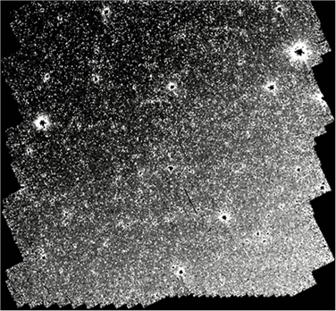
A good place to start is by inspecting the mosaic frame. While you can view the image directly in MOPEX, the overhead associated with JAVA means it is usually faster and more flexible to open it in ds9 or another FITS viewer.
Below is a picture of the quick look mosaic for the ch1 COSMOS data.
The gradient across the field is real and due to Zodiacal light.
3.7 Channel 1 Mosaic
The Mosaic module finds and removes outliers from the individual images, re-samples them onto a common reference frame, and combines them into a final stacked image. There are three possible methods for outlier rejection: "Dual Outlier", "Mosaic Outlier", and "Mosaic Box Outlier". "Dual Outlier" is best suited for low coverage and is discussed elsewhere. "Mosaic Outlier" and "Mosaic Box Outlier" search for pixels which deviate from the median in time and space using multiple overlapping exposures.
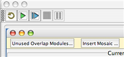
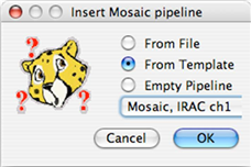
Once you are happy with the output of the Overlap module, you will want to add a mosaic module to your pipeline. You can do this by clicking on "Insert Mosaic..." in the top left of the MOPEX window.
That will bring up the following window.
Check the "From Template" option and then "Mosaic, IRAC ch1" from the drop down menu.
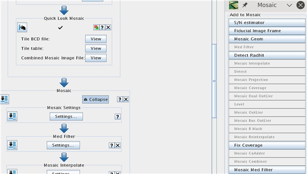
The default mosaic module will be added to your pipeline after the end of the overlap module and a menu of possible mosaic modules will appear.
3.7.1 Mosaic Settings
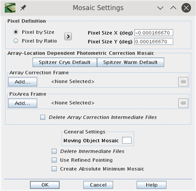
The "Mosaic Settings" dialog box sets several global parameters related to image combination and temporary files.
If you are short on disk space you may want to check the "Delete Intermediate Files" box, which will remove the intermediate data products when they are no longer needed.
Check "Use Refined Pointing" to use the pointing updates in the CBCD files. This is generally not required for data taken after Cycle-2. The pointing refinement involves identifying point sources in the IRAC frames and correlating them with 2MASS source positions. The pointing refinement typically improves the positional error to less than 0.3 arcseconds and removes any systematic offsets. For more information, see Section 5.3.1 of the IRAC Instrument Handbook.
The other boxes correspond to data products not covered by this recipe.
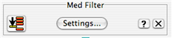
3.7.2 Med Filter
This module filters and removes the background as part of the "Dual Outlier" bad pixel rejection, which is optimal for very low coverage and is not used in this recipe. Remove this module from the pipeline by clicking on the "X" to the right of the box.
3.7.3 Fiducial Image Frame
The "Fiducial Image Frame" sets the parameters for the final mosaic. To configure it, click on "Settings..." in the "Fiducial Image Frame" box. The following dialog box will appear:
Edge padding specifies the number of blank pixels around the edge of the data. A blank area of this width will be placed on all sides of your final mosaic. The default value of 100 is fine for most cases.
Projection specifies the WCS projection. The default "TAN" is used for most astronomical FITS images.
Coordinate System specifies the celestial system for the WCS. Options are J2000, Galactic or Ecliptic. For extragalactic studies, J2000 is the appropriate setting.
The "Use average input orientation" box specifies how the WCS rotation is specified. Leaving this box checked will minimize the size of the final fits image by making the final mosaic as rectangular as possible. However, it is often desirable to specify a fixed rotation to match other data. For COSMOS, uncheck this box and set CROTA2 to 0.00.
When you are finished, click "OK".
3.7.4 Mosaic Interpolation
The "Mosaic Interpolate" module does the first pass interpolation of the data onto the FIF. To configure this module, click on "Settings..." in the "Mosaic Interpolate" box. The following dialog box will appear:
If you have more than a few exposures of dithered data you may wish to use the Drizzle interpolation. This method attempts to recover full sampling of the PSF while minimizing the amount of correlated noise. Drizzle modifies the noise properties of the image in a non-linear manner. For pixfracs > 0.01 the noise will still be correlated, but at a lower level than a linear interpolation. If you are concerned about the noise properties of your images, you should use the default interpolation, which is well characterized, and correct for the noise correlation using the mosaic noise maps.
Drizzle operates by shrinking each pixel by the Drizzle factor, then projecting it onto the final pixel grid. The optimal choice of Drizzle factor depends on the original and final pixel size along with the amount of coverage. The smaller the Drizzle factor the better sampled your final PSF will be. However, if the factor is too small and there are not a sufficient number of exposures, you will not fill the final mosaic. In addition, there is no point in shrinking the pixel to a value smaller than the output pixel scale.
A factor of 0.65 is optimal for the COSMOS IRAC data with an output pixel size of 0.6".
Note that when using the Drizzle interpolation, several of the modules are run twice. In previous versions of MOPEX (releases earlier than 16.3.7), this had to be done manually, but the process is now included in the pipeline automatically. Firstly a linear interpolation is carried out so that MOPEX can run the outlier rejection scheme. Once the outlier rejection masks (RMasks) have been created, MOPEX returns to the Interpolate module and re-runs the interpolation with the Drizzle algorithm, masking out any pixels flagged in the RMasks.
When using Drizzle you will need to remove the "Mosaic Reinterpolate" module later in the workflow.
The "Mosaic Interpolate output subdirectory" specifies the location of temporary files.
3.7.5 Detect
This module detects objects as part of the "Dual Outlier" bad pixel rejection scheme, which is optimal for very low coverage and is not used in this recipe. Remove this module from the pipeline by clicking on the "X" at the right of the box.
3.7.6 Mosaic Projection
This module projects the detection map onto the final mosaic as part of the "Dual Outlier" bad pixel rejection scheme, which is optimal for very low coverage and is not used in this recipe. Remove this module from the pipeline by clicking on the "X" at the right of the box.
3.7.7 Mosaic Coverage
This module configures the image size used for intermediate data products. If you have lots of memory (more than 1GB) you can increase this from the default value and if you are running out of memory you can decrease it at the cost of speed.
3.7.8 Mosaic Dual Outlier
This module conducts the "Dual Outlier" bad pixel rejection scheme, which is optimal for very low coverage and is not used in this recipe. Remove this module from the pipeline by clicking on the "X" at the right of the box.
3.7.9 Level
This module removes false outliers around real point sources as part of the "Dual Outlier" bad pixel rejection which is optimal for very low coverage and is not used in this recipe. Remove this module from the pipeline by clicking on the "X" at the right of the box.
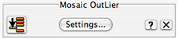
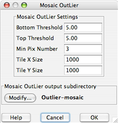
3.7.10 Mosaic Outlier
This module uses multiple frames to reject bad pixels. It measures the median and sigma for each pixel in the final mosaic and flags stray pixels. This method works best when you have coverage greater than 10 so that the sigma and median are well determined.
The "Bottom Threshold" and "Top Threshold" specify the number of sigmas where flagging occurs.
"Min Pix Number" specifies the minimum number of frames required to measure sigma directly.
The tile X and Y size specify the size of the working mosaic in memory.
The default settings are optimal for a coverage of ~10, but if you have higher coverage you should consider increasing the "Min Pix Number" and decreasing sigma.
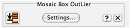
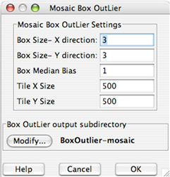
3.7.11 Mosaic Box Outlier
This module preforms outlier rejection using a method similar to "Mosaic Outlier", but considers a window around each pixel rather than just a single pixel. This is useful for moderate coverage where "Mosaic Outlier" may miss some real outliers.
You will need to check the "Use Box Outlier for Rmask" setting in the "Mosaic R Mask" module for the results to propagate through to the final mosaic.
The "Box Size" settings specify the size of the window used to calculate the median in mosaic pixels.
The "Box Median Bias" setting allows you to bias the median used for rejection below the true median by a set number of pixels. This has the effect of rejecting any positive outliers from the median.
The "Tile X Size" and "Tile Y Size" settings control how the final mosaic is broken up during processing to save memory.
The default settings are fine for a final pixel scale of 0.6 arc seconds. If you have a very fine mosaic pixel scale you may want to increase the "Box Size" and "Box Median Bias" settings. You can increase the tile size settings if you have lots of memory.
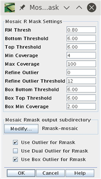
3.7.12 Mosaic R Mask
This module combines the pixel masks and the various outlier rejection masks to generate a master bad pixel mask and a final bad pixel mask for each frame.
"RM Thresh" specifies the minimum fraction of an input pixel covered by a rejected pixel in the final projection for flagging to occur on the input image. Decreasing this value will improve outlier rejection, but also remove a larger number of good pixels. If you have a very fine final pixel scale you should decrease this value.
The "Bottom Threshold" and "Top Threshold" settings specify the upper and lower leaves in sigma for removing pixels flagged by "Mosaic Outlier". The default values are optimal for a coverage of ~10.
The "Min Coverage", "Max Coverage", "Refine Outlier", and "Refine Outlier Threshold" settings only have an effect if you used "Dual Outlier". Setting "Refine Outlier" to anything but zero will cause an error message if the various "Dual Outlier" modules were not run.
The "Box Bottom Threshold" and "Box Top Threshold" settings specify the upper and lower leaves in sigma for removing pixels flagged by "Mosaic Box Outlier". The default values are optimal for a coverage of ~10.
"Box Min Coverage" specifies the minimum number of overlapping frames for pixels flagged by "Mosaic Box Outlier" to be removed.
The three check boxes at the bottom of the window specify which outlier rejection methods will be considered by "Mosaic Rmask". Check "Use Outlier for Rmask" and "Use Box Outlier for Rmask", but uncheck "Use Dual Outlier for Rmask".
3.7.13 Mosaic Reinterpolate
This module re-interpolates the raw data removing pixels flagged by "Mosaic Rmask". This module is not needed if "Drizzle" was selected in the "Mosaic Interpolate" module. Remove this module from the pipeline by clicking on the "X" at the right of the box.
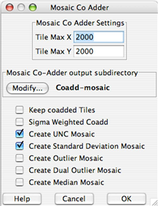
3.7.14 Mosaic Co Adder
This module combines the masked, re-interpolated images into a final mosaic image. You can control
how the co-addition is done and the size of the output images.
The "Tile Max X" and "Tile Max Y" keywords specify how the field is broken up to avoid generating very large files and using too much memory.
The "Mosaic Co-Adder output subdirectory" specifies where the files will be saved.
Checking "Keep co-added Tiles" will keep the tiled images which can be useful if your final image is very large.
Checking "Sigma Weighted Coadd" will generate a weighted average image using the uncertainty maps as the weight. If this is not checked an average image is generated.
Checking "Create UNC Mosaic" will create a mosaic of the uncertainty maps.
Checking "Create Standard Deviation Mosaic" will create an image with the standard deviation of the input pixels as the value at each position.
Checking "Create Outlier Mosaic" or "Create Dual Outlier Mosaic" will cause the relevant bad pixel maps will be mosaicked together. This is useful for determining if real objects were rejected by the outlier detection methods.
Checking "Create Median Mosaic" will generate a median image. This does not conserve flux.
3.7.15 Mosaic Combiner
This module combines the mosaic tiles into a single final image. The only setting is the directory where you would like the images saved.
3.8 Other Channels
In most cases the settings used for channel 1 should be identical for the other three channels. The only changes needed are the names of the input files and removing the "Fiducial Image Frame" modules if you want the images to have the same coordinate system. However, you should verify that the object size and background dependent settings in the Overlap "Med Filter" and "Detect" modules are generating good results.
Before starting the other channels save the channel 1 namelist by clicking on "Save" or "Save As..." in the drop down file menu of MOPEX. Then revert to the beginning of the workflow by clicking on the "Go Back" button in the top left of the "Initial Setup" box at the beginning of the workflow.
This will restore the pipeline to the beginning of the workflow. At this point its a good idea to save the setup with a different name to avoid accidently overwriting the channel 1 setup. This can be done by clicking on "Save As..." in the drop down file menu of MOPEX.
To change the input files, click on "Change..." under "Image Stack File" in the "Initial Setup" box. Select the list of images for the channel you wish to process. Leave "Output Directory" with the same setting as channel 1. The corresponding "Sigma List File" and "DCE Status Mask List" files must also be changed under "Optional Input & Mask Files...". Finally, the "Pmask FITS File" should be changed from the channel 1 bad pixel mask to the relevant channel bad pixel mask.
If you want the pixel positions in the final images to correspond to the same sky positions in all four channels you must remove the "Fiducial Image Frame" module from both the Overlap and Mosaic pipelines. This can be done by clicking on the "X" at the top right of the FIF window. If you change the output directory, you will need to specify the FIF file under "Optional Input & Mask Files..." as the one generated during the channel 1 processing.
Once you have made these changes you can start the pipeline and the next channel will be processed.
3.9 Different Exposure Levels
The above recipe was designed to reduce medium deep (~15 minute integration with more than 10 exposures), blank field IRAC survey data. You will need to change some parameters if your data are of substantially different depth.
Shallower Data:
Change interpolation to default
Add dual outlier mosaic to rejection
Update mosaic rmask to add dual outlier mosaic rejection
For Galactic case with diffuse emission, change settings in mosaic rmask to refine thresholds based on the various outlier rejections
HDR mode:
Same as shallow.
In addition, modify mosaic-rmask pixel fraction rejection to not remove pixels unless a large fraction is flagged. This prevents the low exposure data from being over-flagged.
Deeper Data:
Decrease thresholds for box and temporal outlier.
Decrease pixfrac in drizzle.
Decrease fraction of pixel to be flagged in mosaic-rmask.