In addition to muxbleed in channels 1 and 2, there may be electronic banding, which is manifest as a positive offset for rows that contain bright pixels. This effect is at least an order of magnitude smaller than muxbleed. Electronic banding is more significant in channels 3 and 4 but it is not as significant as the optical banding in those channels (see Section 7.3.2). The BCD pipeline mitigates against these effects. The algorithm finds instances of pull-up and banding and fits the DC offsets on either side of the triggering source to them.
7.2.6 Full-Array Pull-Up
In all four arrays, there is also an effect where an entire image is uniformly offset by some amount of DN’s that is approximately proportional to the total flux or fluence integrated over the array. It is easily noticed in a mosaic when overlap correction is turned off, and when the mosaic contains areas with and without strongly saturated stars. We call this effect “full-array pull-up,” but it is also known as “droop” to the community of users of doped silicon IBC arrays. The effect can go unnoticed when overlap correction is done in the mosaic. It has no significant effect on aperture photometry of point sources or extended sources when a good background mean can be obtained within the same 5 arcminutes x 5 arcminutes image as the source. The effect is largest in channels 3 and 4, and if uncorrected, can lead to significant errors in the derived flux of extended objects, and especially in the brightness of the background itself. It is hard to distinguish the effect from the internal scattering in channels 3 and 4. The IRAC pipeline does not correct this effect.
7.2.7 Inter-Channel Crosstalk
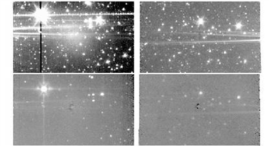
We have detected electronic crosstalk between channels only in the brightest sources that have been observed. All four channels are read out simultaneously, except for the 100/200-second frames in channel 4, for which two/four 50-second frames are taken instead of the long integrations in the other channels, because IRAC is background-limited in channel 4. When a source falls on a pixel of one array, crosstalk may occur in the same pixel location in the other arrays, or in the next pixel read out. Crosstalk appears as a combination of either a positive or a negative offset in the same pixel and the derivative of the signal in the same or previous pixel. As the source is dithered, the crosstalk follows it, and therefore crosstalk appears in the mosaics. It is so weak that we have detected it so far only in channel 3, when the source is in channels 2 and 4, and in channel 4, when the source is in channels 1 and 3. Figure 7.8 shows parts of the mosaics from the off-beams in a dithered observation of a very bright star. The star was observed in channel 1 and 3 FOVs first, so there are residual images in channels 1 and 3 from the bright star. The residual images appear as a diffuse glow near the center. This glow is a combination of the residual images of a very strongly saturated star observed with a Reuleaux dither pattern (cf. Section 3.4), thus effectively smoothed by outlier rejection. The crosstalk appears in channels 3 and 4 as a partial dark ring with a bright core. Crosstalk is not corrected in the pipeline.
Figure 7.8: Channels 1 and 2 (top) and 3 and 4 (bottom) showing inter-channel crosstalk (dark spots near the center of the lower panels).