The architecture of the Combined Electronics (CE) subsystem incorporates two independent and redundant electronics boxes (A & B). The CE subsystem was used to operate both the IRS and MIPS cold instruments, although only one instrument could be used, or even powered up, at a time. While using the IRS, separate circuit boards in the CE handled detector array clocking, detector array signal conditioning, communication with the spacecraft, command and data processing, and engineering data collection functions. When the IRS was operating, all four detector arrays were clocked simultaneously. The on-chip output drivers were independently powered, so that any number of the IRS arrays could be powered on simultaneously. However, the array outputs were multiplexed to the analog signal conditioning circuit so that it was only possible to capture data from one array at a time.
The high-energy radiation environment for the IRS consisted primarily of (1) cosmic ray protons and heavy ions, and (2) solar protons and heavy ions. These particles range in energy from a few eV to over 1 GeV. The peak fluxes and total fluences of these particles vary with the level of solar activity and are on the order of 2-16 protons/cm2/s. This environment caused a variety of effects in the IRS, manifesting as both long-term degradation and abrupt changes in the electronics and optics. The CE was designed to withstand the total radiation dose estimated over a 5-year mission. However, the largest contribution to the accumulated radiation dose damage occured during unusually large solar flares.
2.9.2 Analog Signal Processing
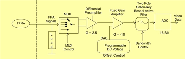
The Si Analog Signal Processing electronics selected and conditioned the signals from the science arrays in use. Figure 2.11 shows a block diagram of the signal path for the output from the Si detector(s). The Si Analog Signal Processing electronics provided signal output and processing for up to five (4 IRS plus 1 MIPS) Si arrays on a 5x4 channel multiplexer with four channels per array. There is no provision for accessing only a subset of an array. The output signal is 1.2 microV/electron. The voltage becomes more negative with increasing detector charge (see Figure 2.12 and Figure 2.13).
Figure 2.11: Si detector output signal path (one of four parallel paths).