3.1.2 Photometry - 24 micron Large Source (Large Field)
For larger (2') sources, dithering purely on the 24 micron array is no longer desirable. Instead, the scan mirror is used to obtain a series of images separated by only a minimal amount and on half-pixel centers; see Figure 3.2 and Table 3.2. The telescope is then redirected to a position > 5' away from the source, and the sequence of frames is repeated to obtain a sky image. The offset to this ''sky'' position is in the scan direction, and the observer specifies the magnitude of the offset. The nominal pattern for these observations is a 1x5 set of images in-scan, separated by 1.5 pixels = 3.825'' for each, followed by a cross-scan spacecraft offset of 4.5 pixels (11.475'') and a repeat 1x5 set of images. In this sequence, frames 1 and 6 are 1 sec shorter than the observer-specified exposure time at both the object and sky positions, and two extra exposures are obtained at object and sky positions per AOR, similar to what happens in the compact source photometry observation sequence described above. As above, the observer specifies only one parameter, the number of observing cycles. The total integration time per pixel in the final images is very nearly equal to ((Nx10)+2)x(Exposure Time) -2 seconds.
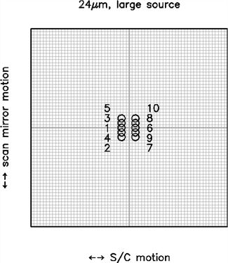
Figure 3.2: Observing a large-diameter source at 24 micron. The positions of image centers in a single cycle of a 24 micron large-source photometry observation are shown relative to the central 64x64 pixels (shown schematically by the grid) of the full 128x128 array. Dither positions are at half-integer pixel offsets in both the scan-mirror direction and the cross-scan direction. An identical set of observations is obtained at an observer-specified sky position offset by >5' in the scan direction. Not shown are the two extra exposures that are obtained for each AOR, which are taken at positions 1 and 6.
Table 3.2: Source positions for 24 μm large source photometry (in units of pixels, the origin being the center of the array).
Frame #
X position
Y position
1
-2.5
0.0
2
-2.5
-3.1
3
-2.5
1.5
4
-2.5
-1.6
5
-2.5
3.1
6
2.0
0.0
7
2.0
-3.1
8
2.0
1.5
9
2.0
-1.6
10
2.0
3.1
As before, Table 3.2 contains the resulting approximate image positions in units of pixels, with the origin taken to be the center of the array. Array distortion and the twist of the scanning mirror with respect to the array columns have not been taken into account in this table, but the positions are good enough for observation planning purposes.