In this chapter, we attempt to summarize the most common things you might encounter in your data. We have not attempted to cover all possible cases, so if you discover in your data something 'interesting' and not listed here, please do not hesitate to let us know.
Figure 7.1 and Figure 7.2 show examples of some of the effects in MIPS-24 data discussed in this chapter. Note that the Si pipelines are summarized in section 5.1.2.
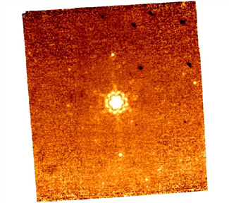
Figure 7.1: Sample MIPS-24 photometry mosaic product (several combined BCDs) from before the read-2 correction (see section 5.1.2); the pipeline attempts to remove gradients across the field (such as the one seen here), but often gradients across the array at the 1-2% level remain. Also, note the dark spots (from pick-off mirror contamination, primarily in upper right), and the bright latents (above and below the bright source in the center). The specific pattern of the dark spots as portrayed here comes from the movement of the telescope+scan mirror during the photometry dithers and are only visible at this level in images which do not use scan-mirror dependent flat fields.
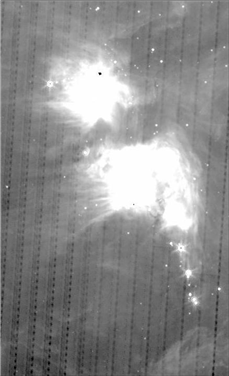
Figure 7.2: Sample subsection of MIPS-24 scan map. Note dark latents from bright objects.