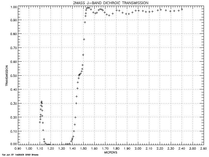
J dichroic transmission Jdt(µ)
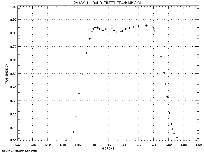
See above for this information, in H-band camera section.
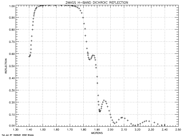
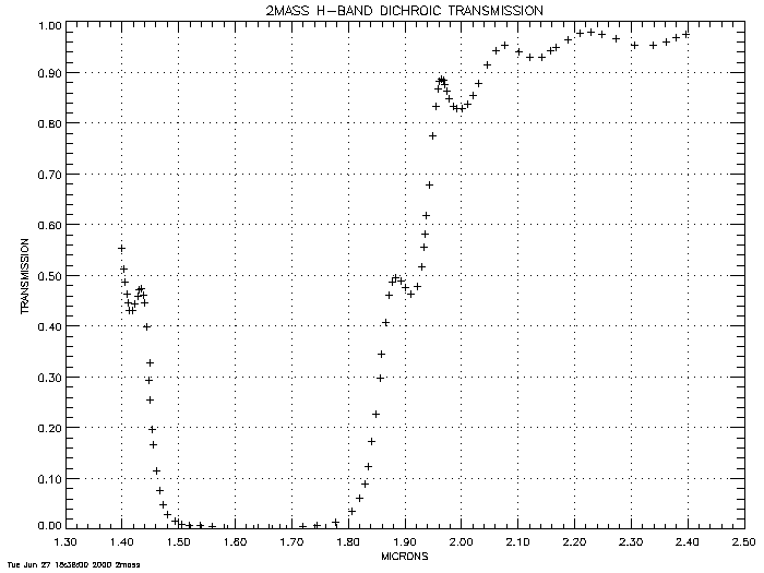
Figure 10 shows the
H dichroic transmission Hdt(µ)
|
| Figure 10 |
H-band Dichroic Mirror Transmission Data Table
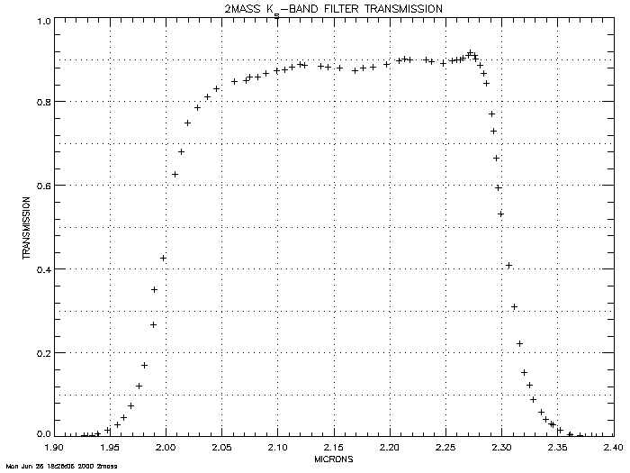
Figure 11 shows the
Ks filter transmission Ksf(µ)
|
| Figure 11 |
Ks Filter Transmission Data Table
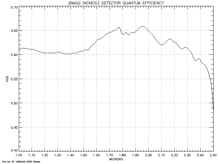
Detectors
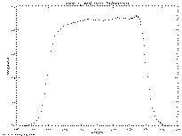
NICMOS3 detector array quantum efficiency Dq(µ)
Figure 12 shows
a representative NICMOS3 array similar to those used
in the 2MASS cameras.
|
| Figure 12 |
NICMOS3 Detector Array Quantum Efficiency Data Table
Total System Response
The following curves are all normalized to unity at the peak.
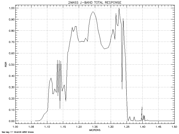
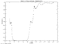
J-Band Total Response RJ(µ)
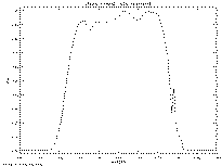
Figure 13 shows
the product of all the J-band factors, including representative atmospheric
transmission at the observatory sites.
The rapidly-varying structure is mostly due to atmospheric absorption
lines and bands, as can be seen in the atmospheric curve
below.
|
| Figure 13 |
J-Band Total Response Data Table
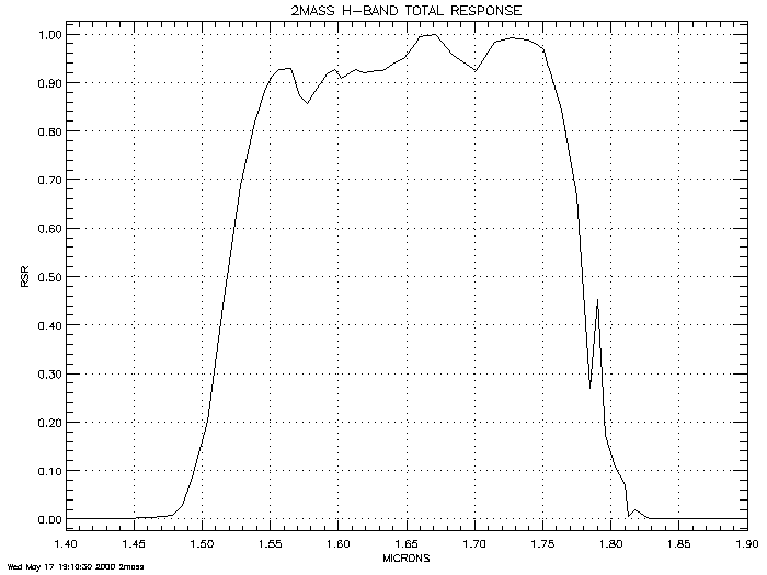
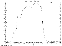
Figure 14 shows the
H-Band Total Response RH(µ), which is
the product of all the H-band factors, including representative atmospheric
transmission at the observatory sites.
|
| Figure 14 |
H-Band Total Response Data Table
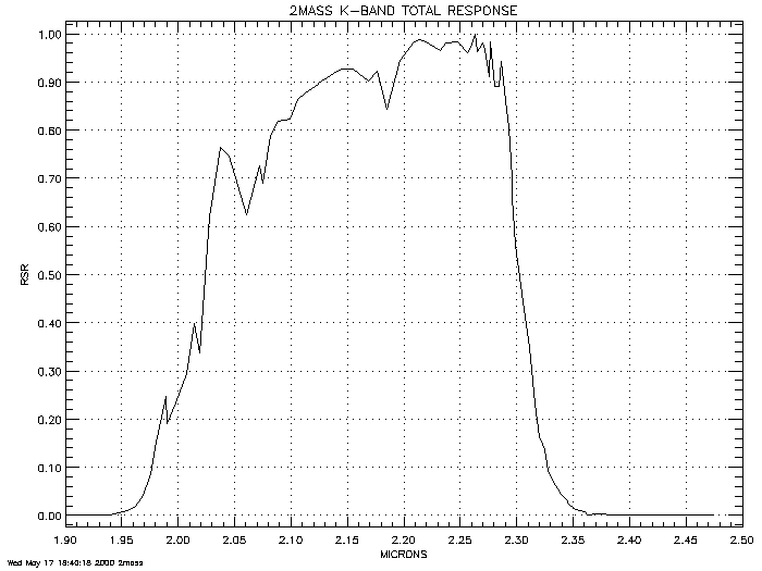
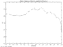
Figure 15 shows the
Ks-Band Total Response RK(µ), which is
the product of all the Ks-band factors, including representative atmospheric
transmission at the observatory sites.
|
| Figure 15 |
Ks-Band Total Response Data Table
Atmospheric Effects:
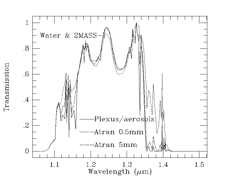
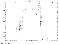
Effect of Atmospheric Water on J-Band Response.
The red edge of the J-band, as defined by the 2MASS filters,
is somewhat sensitive to the amount of precipitable water in the atmosphere.
Figure 16
illustrates the magnitude of the effect for 0.5 mm and
5.0 mm of water vapor, as computed by the ATRAN code, and an
atmospheric model generated by the PLEXUS code, which
incorporates also aerosols and particulates appropriate to the sites.
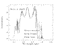
|
| Figure 16 |
We thank Martin Cohen for providing us with the NICMOS3 data (originally
from the manufacturer Rockwell, as obtained by Leslie Hunt),
the atmospheric models, and the resulting total response curves.