FLITECAM Imaging Observing Modes - This document provides an overview of the imaging modes available with FLITECAM. FLITECAM Grism Observing Modes - This document provides an overview of the grism observing modes available with FLITECAM.
This page will cover the following topics:
- FLITECAM SSPOT AOR Checklist
- FLITECAM Imaging Observations
- FLITECAM Spectroscopic Observations
- Other Important Considerations
Other help:
- The FLITECAM instrument page and the FLITECAM section of the Cycle 4 Observer's Handbook give further details of the instrument's capabilities
- The FLITECAM Exposure Calculator for the Grism Mode is here
- Further details on general (non-FLITECAM specific) SSPOT functionality can be found in the SSPOT Pocket Guide and in the SSPOT User Guide .
- For questions not answered by any of this material, please contact the SOFIA help-desk
1. FLITECAM SSPOT AOR Checklist
To speed acceptance of your Phase 2 AORs, you may wish to consider the following checklist.
- Does your source fit within the field of view of FLITECAM given any rotation of field (i.e. your object must not be any bigger than 8' across in any dimension)? If yes, are you nodding far enough so that you are nodding off of the source? If not, have you specified your mosaic strategy?
- For dithered observations, the exposure time will be set in the dither control panel. The user will set the exposure time per dither position and this will be used to calculate the total exposure time. See details below.
- For imaging mosaics of extended objects larger than the FLITECAM field of view, did you set up the mosaic offsets so that there is adequate overlap so that there will be no gaps in coverage regardless of the sky orientation at the time of observation?
- For imaging extended regions, the user can select the "Nod Off Array" mode, which will require setting the nod angle and throw. Nods can be in array or sky coordinates (sky is the default). Use pull down menu in "Images" tool to determine nod direction and throw with a specific AOR to ensure nodding onto blank sky. All observations sould be checked by looking at WISE, Spitzer, MSX, or IRAS images to make sure that the nodding configurations are set up properly.
- If performing spectroscopic observations did you check to make sure that nods off the array are on to clean sky, and that nods along the slit are not on top of another target? All observations should be checked by looking at WISE, Spitzer, MSX, or IRAS images to make sure that the nodding configurations are set up properly.
- Did you prioritize your targets if you have some that are more important to observe than others? Make sure you have set up your Observing Priority . Very importantly, make sure ALL observations (AORs) for a particular target have the same Observing Priority.
- Did you prioritize the individual observations (AORs) for each target? Make sure you have set up your preferred observation Order .
- Did you provide comments for non-standard observations or special requests?
- Are your observations for FLITECAM-HIPO, or for FLITECAM on its own? The exact configuration greatly changes the minimum exposure times per band as well as observed backgrounds, and as a result changes the required subarray size for imaging filters. Check with your Support Scientist for any clarification!
2. FLITECAM Imaging Observations
2.1. Setting up Imaging Observations - Stare and Dither
While the FLITECAM detector size is 8'x8', the optical field stop results in a circular FOV with a diameter of 8'. The standard observing strategy for imaging is to perform small dithers around the source which allows for flat field construction, background subtraction and array artifact removal during the data reduction phase. Note that the best imaging is within the 5.6" diameter and this is the standard size used in the dither data reduction package. We now also strongly suggest that dithers patterns use the 9-pt template in SSPOT, to improve background subtraction and bad pixel masking. This will be the default for FLITECAM in SSPOT starting in Cycle 5.
Within SSPOT, observers can set up dithers to ensure adequate blank sky for background subtraction and flat field generation during the data reduction process.
Figure 2-1 , below, shows an example of the FLITECAM FOV on the target W3 with 4 different overlays that are relevant to FLITECAM.
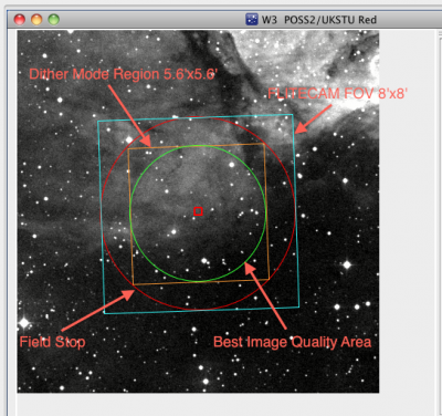
Figure 2-1 - FLITECAM field of view (FOV).
1. FLITECAM Field of View (Blue square 8'x8')
2. The circular field stop (in Red).
3. The imaging area used in the dither pipeline (Orange Square 5.6'x5.6')
4. Finally, the circular area with the best detector response (Green Circle).
For imaging mode observations, the GI can choose to stare (see Figure 2-2 ), but most observations will require a dither ( Figure 2-3 ). The GI can specify the number of dither positions and the offset between positions. In SSPOT the GI can select a specific dither pattern, 3,5,9 dithers or a custom number of dithers (from the “Set Dither Pattern” button). For a point source a typical dither offset will be 20-30" depending on the seeing. If the source is extended or the field is crowded then sky observations are needed and the nod size can be increased. When observing at the longer wavelengths where a sub-array is required, the dither offsets will need to be reduced so that each observed position is within the sub-array in order to achieve the best data reduction.
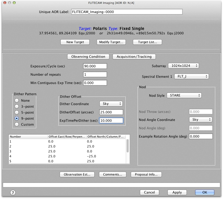
Figure 2-2 - This figure is the top level FLITECAM Imaging AOR panel. The dither pattern is selected on the left side, and currently reccomnended to be 9-pt with a dither offset (in sky coordinates) between 20-30" for point sources. The exposure time at each point in the dither should be set in the Dither Offset box in the center, which will then automatically update the Exposure/Cycle towards the top of the panel. ( Figure 2-3 ).
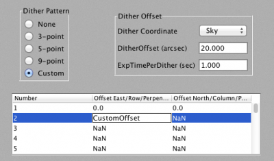
Figure 2-3 - This figure highlights the dither setup area that will be the main focus of user-entered AOR parameters. In this case a custom dither pattern has been selected. Note that the dither pattern initially only defines the base position (0, 0) and additional positions can be defined by double clicking on an offset number (with NaN signifying undefined values) and entering a valid (numeric) offset amount. The desired exposure time at each point in the dither should be set in the dither offset box, which will then automatically update the Exposure/Cycle.
In Figure 2-4 below, SSPOT has been used to set up a sample 5pt dither on W3. For simplicity, the square 8'x8' FOV (1024x1024 sub-array) has been used as the overlay.
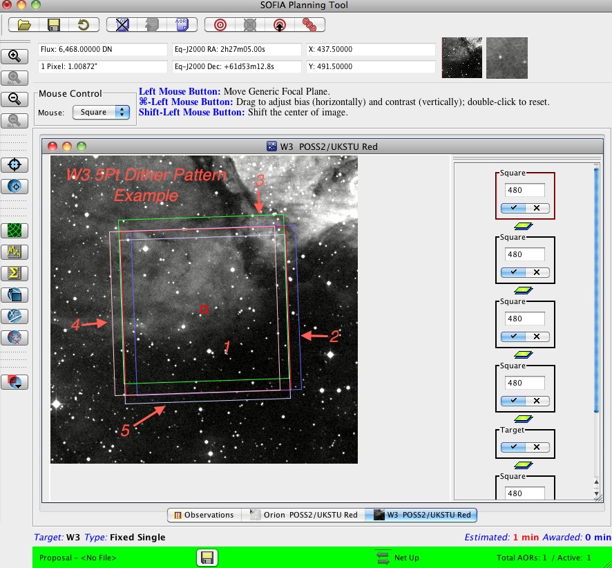
Figure 2-4 - This figure shows an example of a FLITECAM 5-point dither pattern.
If the source is larger than the FLITECAM field of view, then the GI will need to either mosaic the images or to use the “Nod Off Array” mode. "Nod Off Array" is selected in the main AOR control panel (see Figure 2-5 , below. The user selects “Nod Off Array” in the Nod parameters box (top right section of the panel) and then specifies how far to nod using “Nod Throw” and the angle of the nod throw with “Nod Angle”. It may be that the nod throw and angle cannot be chosen until flight plans are finalized, as the rotation of field is indeterminate until that time. In the AOR example below ( Figure 2-5 ), the target is M82 and the nod is defined with an angle of 0° and a throw of 240''. Also shown is a screen shot of the SSPOT imaging tool showing a DSS image of M82 with the current AOR overlay on the source ( Figure 2-6 ).
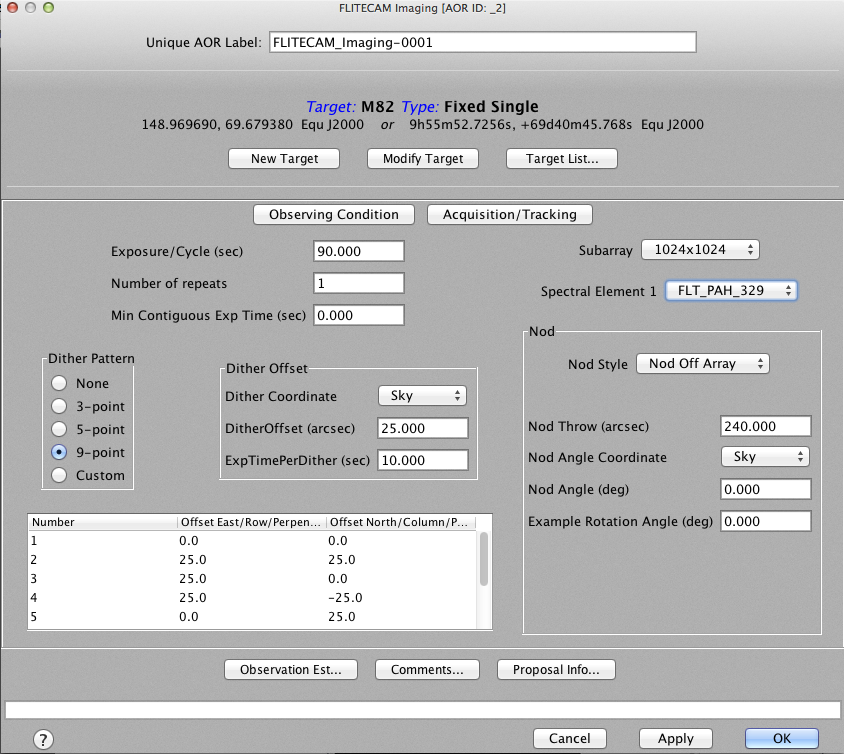
Figure 2-5 demonstrates the “Nod Off Array” mode, selected along with a 240” throw at an angle of 0°. These parameters will be reviewed and revised once flight plans have been generated to ensure that nodding off the array will be onto blank sky.
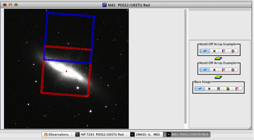
Figure 2-6 shows an SSPOT screen shot of a “Nod Off Array” observation. In this case the original dither pattern, in red, is centered on the source (M82) and the nod off, in blue, is nodded at 0° with a 240” throw. Once flight plans are mature, the nod throw and angle can be adjusted to ensure blank sky in the “off” position.
Mosaicking involves nodding the telescope to a number of positions on the sky and dithering at each position. At present, there is no mapping mode available to create a mosaic automatically. Instead, the GI must specify the coordinates for each position manually and enter them as independent observations. However, one must keep in mind that we cannot control the orientation of the field of view on the sky. The mosaic positions should be specified close enough to one another that they will overlap for ANY field orientation, allowing the GI to combine them into an uninterrupted map in the post-processing stages. This can be tested by changing the "Example Rotation Angle" in the AORs and reloading the AORs into the visualizer. In addition, for long integrations, and for sources in parts of the sky that rotate quickly, different elements of the mosaic may sample the source at different position angles. An example of this with a mosaic of W3 is shown below. In this example, it is likely that given the small overlap of the fields there will be gaps in the mosaic coverage at certain field orientations. Additionally however, let's assume that the GI needs 10 minutes per position to integrate down to the level required of the science. Let's also assume that for this source, the sky is rotating rapidly enough that the telescope needs to perform a LOS rewind after every 10 minutes. In that case there would be a LOS rewind after each element is sampled in the mosaic. The example below shows a two-position mosaic starting centered on the source.
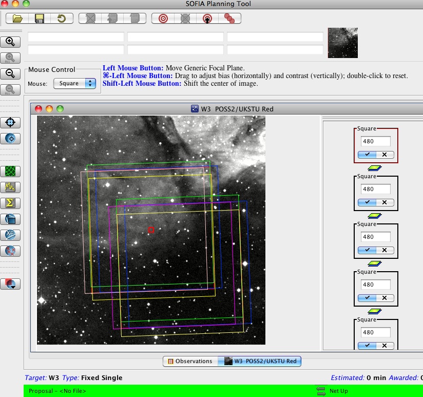
Figure 2-7 shows an example of a two position mosaic starting at the center of W3 (red square).
3. Spectroscopy Observations with a 2" slit
3.1. FLITECAM Grism Observing Modes
Click on the link to the right to download the "FLITECAM Grism Observing Modes Document" (W. Vacca) for more details: FLITECAM Grism Observing Modes
3.2. Setting up Spectroscopic Observations
Note that the FLITECAM slit is a continuous cut in a slit mask that is slid into the optical beam for spectroscopy (one side is 2"x60" and the other is 1"x60").
If the object is a point source and the slit orientation is irrelevant then the GI can "Nod along the slit" in the SI reference frame. Note the slit orientation is determined by the flight plan and cannot be specified apriori by the GI. Therefore, if a preferred slit orientation is required because sources near the slit may appear on the slit when nodded, then the GI should choose to "Nod off slit" and the GI may need to restrict the possible position angles of the off slit observation position.
Figure 2-8 and Figure 2-9 , below, illustrate a “Nod Along the Slit” AOR for FLITECAM Spectroscopy Mode. The K wide order sorting filter is selected with the C grism (FLT_C3_Kw), and the nod throw has been changed to the now-reccomended value of 20" along the low resolution slit (FLT_SS20). The target, HD 40335 is used to illustrate this mode.
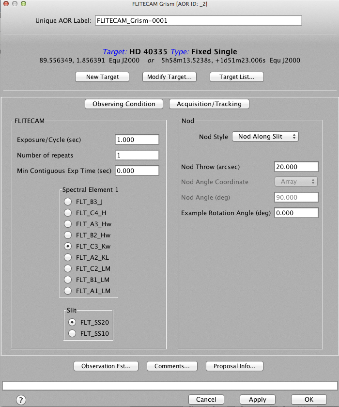
Figure 2-8 shows the AOR configuration for a FLITECAM spectroscopic observation with an "on slit" nod. Since the nod is along the slit, it must be performed in Array coordinates with a fixed nod angle of 90°.
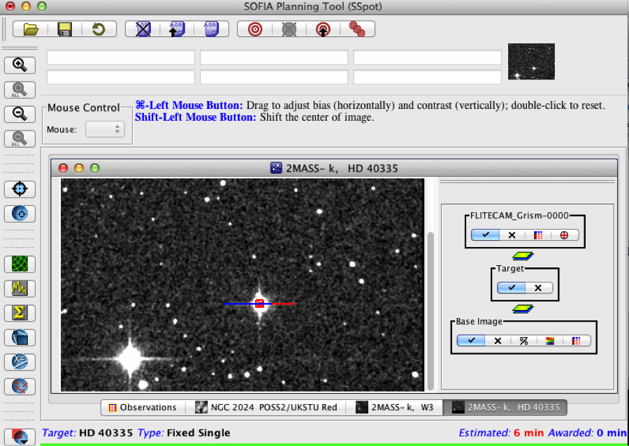
Figure 2-9 shows the overlay for the "on slit" nod on the target HD 40335. Since the angle of the slit is unknown until the flight planning is complete, the final AOR will need to be checked once the flight plans are finalized to ensure that there is no contamination from nearby sources. In this example, there are no targets near enough to the source to cause problems.
In some cases, the GI may wish to nod off slit in order to avoid nodding onto extended emission or nearby sources. This is done using "Nod Off Slit" mode, which can be defined using the Nod Style entry in the Nod Parameters box. The GI must set the nod throw and angle (can be set in Sky or Array coordinates) but since the slit orientation cannot be adjusted, these parameters may be revised after the flight plans have been completed to ensure nodding onto blank sky.
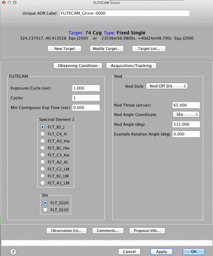
Figure 2-10 demonstrate how to set up the AOR parameters for a "Nod Off Slit" spectroscopic observation.
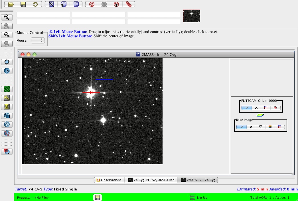
Figure 2-11 displays the overlay of the FLITECAM AOR "Nod Off Slit" mode on 74 Cyg as shown in the main AOR panel above. The nod angle of 315° and a nod throw of 65" is used in order to avoid other sources in the field.
This is a second FLITECAM AOR example of a "Nod Off Slit" mode selected using an angle of 315 degrees and a nod value of 65" in order to avoid other sources in the field shown in the overlay in the right figure.
The current observing overhead estimates for spectroscopy mode are high to allow time for source acquisition, positioning, and imaging of the source position on the slit before beginning actual data acquisition. For subsequent spectroscopy modes of the same target, the overhead will be significantly less, and the actual overheads as enacted in SPT/SSPOT will be revised for Cycle 5. Please consult the FLITECAM instrument scientist via the SOFIA Help Desk ( sofia_help@sofia.usra.edu ) for more information.
Note that observation Estimates are available on the SSPOT site by clicking on the button entitled "Observation Est" from within the FLITECAM Spectroscopy GUI.
4.1. Specifying Visual Magnitude of Target
It is important to check on the visual magnitude of each science target. If the target is brighter than 14th magnitude and point-like (i.e., compact), then the GI should give the magnitude and the reference wavelength (band V, B or R) in the "Acquisition Tracking" pop-up window (see Figure 2-12 , below). If the object is fainter than this, the GI should select "Invisible" from the "Visible Wavelength" pull-down (any value in the "Visible Magnitude" field will then be ignored). If the target is brighter than 14th magnitude in the visible and point-like, the telescope can guide on the source directly. This greatly decreases observation set-up overhead and translates to more time taking science data on the target during a scheduled flight leg.
It is also a good idea to fill in the IR flux of the source at a reference wavelength close to the one being observed. This helps the observer to assess whether or not the observations are proceeding as expected.
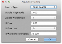
Figure 2-12 shows the Acquisition Tracking dialog box in which GIs should specify characteristics of their science target for the purpose of guiding during the science observations.
In the "Observing Condition" pop-up window (see Figure 2-13 , below), there are two keywords that help a GI prioritize their observations. The pull-down menu for "Observing Priority" refers to the relative priority of a specific science target with respect to other science targets within the GI observing program . This is used by the flight planners to determine which observations to schedule if for some reason not all of the targets within the GI's program can be observed. The GI can select a target to be either Low , Medium , or High priority. If all of the GIs targets are of equal interest (as for, say, a survey of many dozens of targets), then they should all be set to Medium (the default). Setting all of the targets to High priority will not ensure that they all are observed. If High priority is used for some targets, other targets must be set to Medium and/or Low priority as well.
The second level of observation prioritization is given by the "Order" field. This allows the GI to specify the priority of the AOR used to observe a single science target . This field allows the GI to numerically list the priority of their observations of a single target within an observing leg. The length of an observing leg is rigidly defined during flight planning and cannot be extended in flight. If, for instance, aquisition takes an unusually long time, or if there are any hardware/software failures during the observing leg for a particular target, it may be that not enough time will remain for all of the scheduled observations of the target to be performed. For this reason we ask the GI to prioritize the observations of a particular target using the "Order" field. The first observation to be executed will be Order=1, the second will be Order=2, and so on.
The GI may be worried about the calibration accuracy of their observations. We have in place in the SSPOT tool a pull-down menu that allows the GI to let us know if accurate calibration is important to their program with the "Required Calibration Accuracy" menu. We expect to deliver flux calibration at the level of 20% absolute accuracy, and while we expect to do better than that in many cases, we can make no guarantees to do better than that for a particular observation. However, there are times in flight (i.e. after the first 2 hours) where calibration is usually better. If the GI sets the "Required Calibration Accuracy" to High , the flight planners will make a best effort to put these observations in the flight plan at times when we usually have better calibration accuracy.
The GI may also be concerned about needing extra sensitivity for a particularly challenging observation. Generally, the higher the aircraft flies, the less water vapor overburden and the greater the sensitivity of FLITECAM. If a GI has a particularly faint target, s/he may wish to change the "Required WV Overburden" from Nominal , to Low or Very Low . However, like the calibration accuracy pull-down menu, we cannot guarantee the GI that the observations will be taken under low water vapor conditions. However, the flight planner will make a best effort to accommodate such requests.
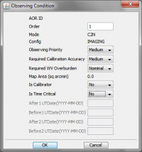
Figure 2-13 shows the Observing Condition window, which allows the setting of target priorities and observing conditions.
4.3. Including Instructions to the Observers/Planners
It is very likely that most or all of the GI's observations will be performed without them onboard the aircraft. Therefore it is vitally important that the GI convey any special requests or procedures to the observer through the comment tool. These comments will be read by the observers in flight. They will also be viewed by flight planners. Therefore any comments to either one of these groups should be written in the text field of this pop-up window (see Figure 2-14 , below). These comments will be reviewed by your Support Scientist during the Phase 2 process to ensure comments are thorough, clear, and understood.
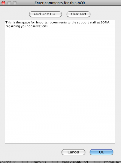
Figure 2-14 shows the AOR Comments window, which allows GIs to provide AOR and target specific information useful for FLITECAM instrument scientists and flight planners.