Introduction
HAWC+ is a 2nd generation instrument that will be commissioned in 2016, during Cycle 4. HAWC+ specific instructions and reminders of general issues are given in the following topics below. Note that all menu selections and selectable options are boldfaced , field names appear as in SSpot, and text to enter into SSpot is displayed in Courier New . The brief instructions below will be expanded to include details after the observing modes have been characterized in-flight. Before preparing detailed HAWC+ observations in SSpot, please read the HAWC+ section of the Observer's Handbook .
HAWC+ observing modes are covered in three Astronomical Observation Templates (AOTs) in SSpot, HAWC PLUS Total Intensity, HAWC PLUS Polarization, and HAWC PLUS OTFMAP, which correspond to standard imaging with two position nod-match-chop, polarization with two position nod-match-chop, and scan mode imaging respectively.
In the main panels for each AOT, the PassBands correspond to filters with the characteristics given in Table 10-1 . The mean wavelengths are as follows:
HAW_A: 53 μm
HAW_C: 89 μm
HAW_D: 154 μm
HAW_E: 214 μm
The Astronomical Observation Requests (AORs) should be created as described in the SSpot User Guide . The most critical information we require at this time are accurate target coordinates and any desired chop angles to avoid areas of extended emission (as seen in Herschel images, for example).
Many of the fields in the AOTs are self-explanatory, and many general instrument-independent parameters are covered here in the FORCAST page for SSpot. Please read through the brief descriptions below and consult with your support scientist for help with filling out the remaining fields in the AORs. There are many of the AOR parameters that are kept as constants to simplify observations with HAWC+. These can be changed by the support scientist after discussing the observations, but the defaults either in SSPOT or given in the sections below are the values that are preferred.
If you have any questions, please contact the SOFIA help-desk .
HAWC+ Available Field of View
For polarimetry observations, the current configuration of HAWC+ lacks a second T polarization state array; as such, the field of view is reduced to approximately half in the detector's X direction (the first element of the Field of View in Table 10-1). Total intensity observations are unaffected and can use the whole field of view via the R polarization state. To state it clearly, these are the available field of views for both TOTAL_INTENSITY and POLARIZATION observations.
| Band | Wavelength | TOTAL_INTENSITY FOV (arcmin) | POLARIZATION FOV (arcmin) |
|---|---|---|---|
| HAW_A | 53 μm |
2.7x1.7 |
1.3x1.7 |
| HAW_C | 89 μm | 4.2x2.6 | 2.1x2.6 |
| HAW_D | 154 μm | 7.3x4.5 | 3.6x4.5 |
| HAW_E | 214 μm | 8.0x6.1 | 4.0x6.1 |
The images below are included to illustrate and underscore this difference. In both, the HAW_A, HAW_C, HAW_D, and HAW_E FOV's are shown by the pale blue, green, orange, and red boxes respectively.
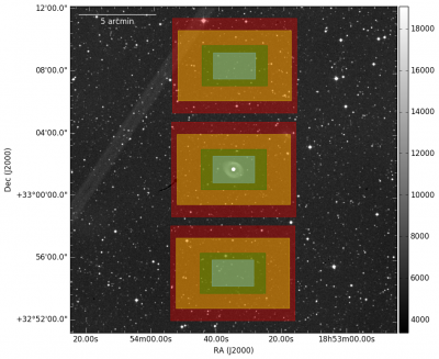
TOTAL_INTENSITY C2N/NMC Observations, chop throw of 400" at an angle of 0 degrees.
The above image shows the available FOV in TOTAL_INTENSITY observations using a 400" chop throw at 0 degrees in a typical C2N/NMC observation.
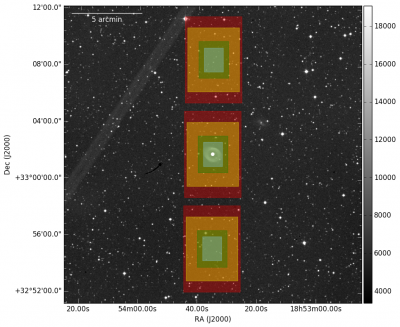
POLARIZATION C2N/NMC Observations, chop throw of 400" at an angle of 0 degrees.
The above image shows the available FOV in POLARIZATION observations using a 400" chop throw at 0 degrees in a typical C2N/NMC observation.
Observing Condition & Acquisition / Tracking
To better assist in our observations of your target, please fill out the relevant details in the Observing Condition & Acquisition / Tracking window.
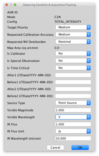
Of particular importance and interest are the final 6 parameters in that window for tracking purposes; please choose representative values for your target when possible. The visible wavelength will help us quickly assess whether the source itself can be used as a tracking source for the SOFIA visible tracking cameras of if we should plan for an alternate tracking star/source.
Total Intensity Imaging - NMC/C2N
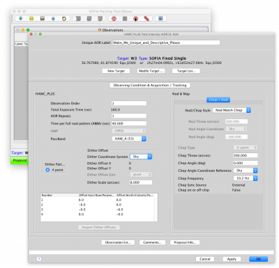
Overall description: four dither points are created symmetrically about the central object coordinates. At each dither position, chopping is started at the given throw and angle and the telescope is nodded between two symmetrically located points 180 degrees seperated from each other. As commissioning of HAWC+ progresses, this sequence will be refined and may include additional calibration observations during the sequence described.
Real World Example
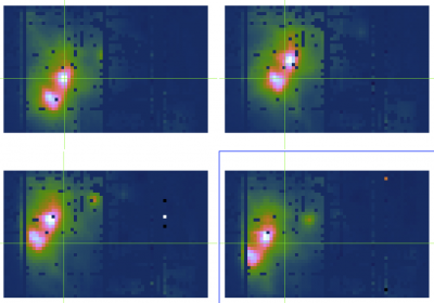
The image below shows a source being dithered between 4 positions. The green crosshairs give the position of one of the sources and is at the same physical location for each image, showing the image movement.
| Editable AOR Parameter | Description |
|---|---|
| Unique AOR Label | Important for communication, so please make it descriptive. |
| Observation Order | Used for prioritizing observations per target; if your accepted proposal contains observations in HAW_A and HAW_E, and the HAW_E observations are more important, it should have a correspondingly lower observation order. |
| AOR Repeats |
Number of times to repeat the full dither sequence. Increase this number to increase the total exposure time. |
| Time per full nod pattern (ABBA) | For SOFIA Cycle 5: This should be always set to 40 seconds to maintain observational efficency and ensure proper sky subtraction. |
| PassBand |
For SOFIA Cycle 5: HAW_B is unavailable. |
| Dither Scale |
Distance (in arcseconds) from the object's coordinates to move for the dither positions. Note: Changing the passband will change the default dither scale value appropriately, dithers should be no smaller than these default values to ensure enough source motion on the focal plane. |
| Chop Throw | The maximum chop throw is somewhat dependent on the observational field since a tracking source is required on the Focal Plane Imager (FPI) camera, but usually 400 arcseconds is routinely achievable. |
| Chop Angle | SOFIA’s chop angle is counted from the north and increases in the direction of decreasing RA, which is the opposite of what an astronomer would be used to. |
| Chop Frequency | Arbitrary chop frequencies are NOT supported for HAWC+: the chop frequency must be an integer multiple of the detector readout. Therefore, only 10.2 and 16.9 Hz are supported and 10.2 Hz is the default. |
An aside on NMC/C2N overheads with HAWC+
NMC/C2N observing modes, either with or without polarization observations, are very time intensive and are subject to large observational overheads waiting for the telescope and/or secondary mirror assembly to complete chop/nod/dither movements. Estimated overheads before first flights were purposefully large (factors of 10!) and these large overhead factors remain in SSPOT 3.3.0.1. Reduced overheads based on flight data analysis are becoming available and are near factors of 3 or 3.5; the support scientist(s) for HAWC+ in Cycle 5 will be using better estimates of overheads for observational planning as they become available.
Polarization - NMC/C2N
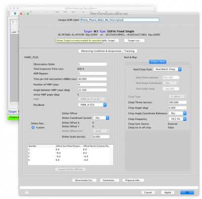
SSPOT 3.3.0.1 Polarization AOR parameters
Overall description: four dither points are created symmetrically about the central object coordinates. At each dither position, chopping is started at the given throw and angle and the telescope is nodded between two symmetrically located points 180 degrees separated from each other. After each ABBA nod sequence, the HWP is rotated to the next angle; this continues until the HWP has gone through four angles, after which the telescope moves to the next dither position and repeats. As commissioning of HAWC+ progresses, this sequence will be refined and may include additional calibration observations during the sequence described.
Real World Example
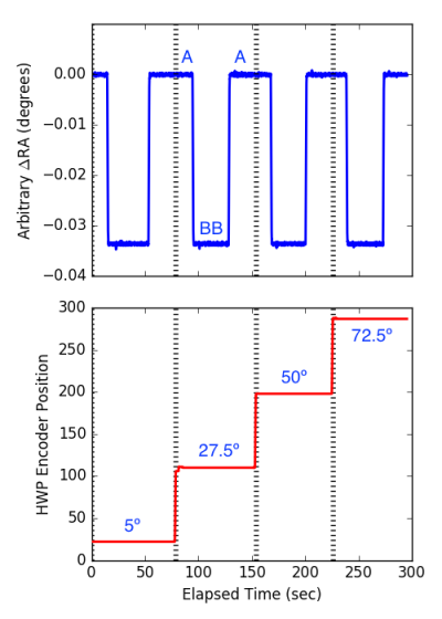
The plots below show both the change in source RA (illustrating the nodding of the source) and the half-wave plate angle for a single dither position of a polarization sequence; the dashed lines denote the completion of a half-wave plate observing sequence. This same sequence (4 half-wave plate angles) is repeated for each dither position to move the source appreciably and assist in the correction of bad/missing pixels. The source is being chopped during this entire sequence (and accounts for the "thickness" of the blue source RA line) but is not specifically highlighted here. The standard ABBA nod sequence is highlighted, and the half-wave-plate angles are highlighted as well.
| Editable AOR Parameter | Description |
|---|---|
| Unique AOR Label | Important for communication, so please make it descriptive. |
| Observation Order | Used for prioritizing observations per target; if your accepted proposal contains observations in HAW_A and HAW_E, and the HAW_E observations are more important, it should have a correspondingly lower observation order. |
| AOR Repeats |
Number of times to repeat the full dither sequence. Increase this number to increase the total exposure time. |
| Time per full nod pattern (ABBA) | For SOFIA Cycle 5: This should be always set to 40 seconds to maintain observational efficency and ensure proper sky subtraction. |
| Number of HWP Steps |
For SOFIA Cycle 5: Always 4 |
| Angle between HWP Steps | For SOFIA Cycle 5: Always 22.5 |
| PassBand | For SOFIA Cycle 5: HAW_B is unavailable |
| Dither Scale |
Distance (in arcseconds) from the object's coordinates to move for the dither positions. Note: Changing the passband will change the default dither scale value appropriately, dithers should be no smaller than these default values to ensure enough source motion on the focal plane. |
| Chop Throw | The maximum chop throw is somewhat dependent on the observational field since a tracking source is required on the Focal Plane Imager (FPI) camera, but usually 400 arcseconds is routinely achievable. |
| Chop Angle | SOFIA’s chop angle is counted from the north, and increases in the direction of decreasing RA, which is the opposite of what an astronomer would be used to. |
| Chop Frequency | Arbitrary chop frequencies are NOT supported for HAWC+: the chop frequency must be an integer multiple of the detector readout. Therefore, only 10.2 and 16.9 Hz are supported and 10.2 Hz is the default . |
Scanning - OTFMAP - Box (a.k.a. raster, waffle)
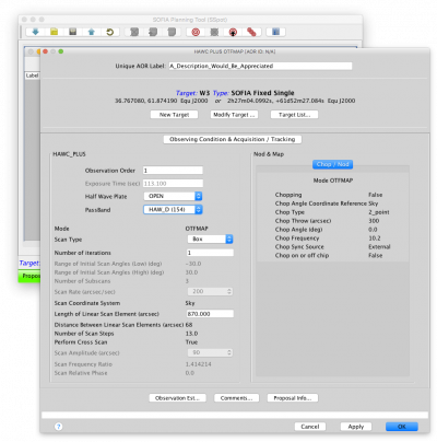
Overall description: The telescope is driven in a linear fashion at the specified rate in one direction for the given length and then moved perpendicularly before scanning in the reverse direction—similar to how one would mow a very large lawn. This is continued until a square area is covered, after which the process repeats in the perpendicular direction to cross the same areas in the perpendicular direction. For optimal reduction and coverage, three scans are performed, each at a slightly different starting angle to improve coverage and provide reduction robustness against systematic effects. As commissioning of HAWC+ progresses, this sequence will be refined and may include additional calibration observations during the sequence described.
Real World Example
The following images demonstrate the actual scan modes used in flight. The white box shows the TOTAL_INTENSITY field of view, the orange line shows the actual path as taken by the telescope, and the background images are the resulting image after the scan data is reduced.
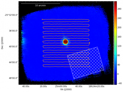
In the above image, the scan starts at the bottom right, pauses midway through to obtain an estimate of tracking performance (the orange dot on the middle right) and then proceeds until the end.
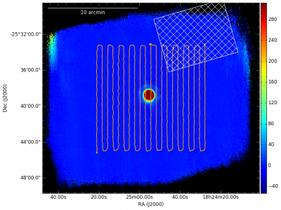
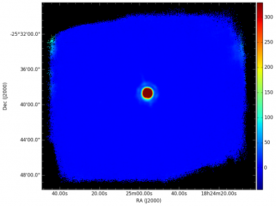
In the above image, the scan starts at the upper right, pauses midway through to obtain an estimate of tracking performance (the orange dot on the middle of the top) and then proceeds until the end. The two directions are then combined to obtain the image below.
| Editable AOR Parameter | Description |
|---|---|
| Unique AOR Label | Important for communication, so please make it descriptive. |
| Observation Order | Used for prioritizing observations per target; if your accepted proposal contains observations in HAW_A and HAW_E and the HAW_E observations are more important, it should have a correspondingly lower observation order. |
| AOR Repeats |
Number of times to repeat the full dither sequence. Increase this number to increase the total exposure time. |
| HWP | For SOFIA Cycle 5: Always Open |
| PassBand | For SOFIA Cycle 5: HAW_B is unavailable. |
| Scan Type |
Box |
| Number of Iterations | For SOFIA Cycle 5: Must be greater than or equal to 3 |
| Length of Linear Scan Element | Scan will always be square, so this is the length of one side of that square. |
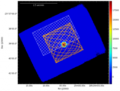
Scanning - OTFMAP - Lissajous
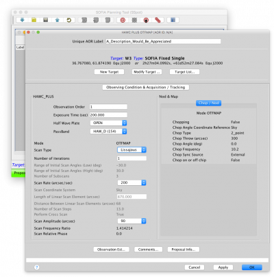
Overall description: The telescope is driven to follow a parametric curve at a non-repeating period; as the scan progresses longer in time, more and more of the area defined by a scan amplitude will be covered. As commissioning of HAWC+ progresses, this sequence will be refined and may include additional calibration observations during the sequence described.
Real World Example
The following images demonstrate the actual scan modes used in flight. The white box shows the TOTAL_INTENSITY field of view, the orange line shows the actual path as taken by the telescope, and the background images are the resulting image after the scan data is reduced.
| Editable AOR Parameter | Description |
|---|---|
| Unique AOR Label | Important for communication, so please make it descriptive. |
| Observation Order | Used for prioritizing observations per target; if your accepted proposal contains observations in HAW_A and HAW_E and the HAW_E observations are more important, it should have a correspondingly lower observation order. |
| Exposure Time |
Total duration of the scan; 200 seconds is recommended for most observations. |
| HWP | For SOFIA Cycle 5: Always Open. |
| PassBand | For SOFIA Cycle 5: HAW_B is unavailable. |
| Scan Type |
Lissajous |
| Number of Iterations | For SOFIA Cycle 5: Must be greater than or equal to 3 |
| Scan Rate | For amplitudes less than 100 arcseconds the scan rate should be less than 200 arcseconds/sec. |
| Scan Amplitude | Size varies per band to be comparable to the HAWC+ FOV in that band. Defaults should be used. |