The scan map mode is designed to provide efficient mapping of large areas on the sky. A ramp motion of the scan mirror compensates for continuous telescope scanning motion, freezing the images on the arrays. The scan map mode avoids having to repoint and stabilize the telescope between exposures. A schematic representation of this is shown in Figure 3.16.
Redundant images greatly improve the reliability of MIPS data, especially from the germanium arrays (e.g., to help remove cosmic ray effects, or uncertainties in the calibration of highly extended emission in a map). A single scan pass (or ''leg'') provides multiple redundancy at 24 and 70 micron (Figure 3.17). However, single scan legs provide only single redundancy at 160 micron at the slow and medium scan rates, and only 1/2 coverage at the fast scan rate (Figure 3.18 and Table 3.5). Redundant coverage at 160 micron, which was strongly recommended, could only be obtained if the observer specified at least two overlapping scan legs; it was strongly encouraged that observers obtain at least 4 images of a 160 micron target if the 160 micron data were important to the science goals. At 24 micron, another scan map at a later time was needed to identify asteroids; most asteroids at 70 micron should be identifiable by the ratio of their 24 and 70 micron colors. At all bands, a second map is desirable to remove transient events.
It should be emphasized that the Scan Map AOT does not intrinsically provide any data redundancy at 160 micron at any scan rate. Those who wish to have high-quality scan data at 160 micron must use data with repeat coverage of the map area, either using sub-array scan leg offsets or repeat visits to the map area. See the discussion of data redundancy for the 160 micron Photometry AOT, section 3.1.
As a result of the on-orbit realities with the Ge detectors, for full sky coverage at comparable signal-to-noise, it was recommended that observers should step by at most half-array widths (2.5') in the cross-scan direction between scan legs. If 160 micron data was required, observers were instructed to design their observations to include sufficient redundancy at all locations in space, i.e., step by no more than 2.5' and preferably 2' to avoid the inoperative readout.
Figure 3.16: Schematic representation of synchronization of scan mirror motions, telescope scan, and stimulator flashes.
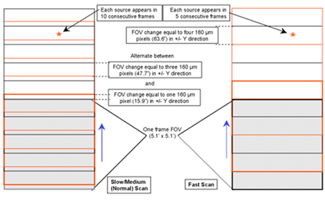
Figure 3.17: Operation of 24 and 70 micron arrays during scan mapping. During normal operation, every source is observed ten times in a single pass; during fast scan, each source is observed five times.