The first DCE of every commanded sequence of observations (e.g., data with the keyword DCENUM=0) have a shorter exposure time and are depressed in response by 10-15%. The photometry AOTs are designed such that these ''extra'' frames can be discarded. Although there could be useful information in these frames, they are omitted from the automated post-BCD mosaics. You will be sent all BCDs (including those with DCENUM=0), so if you reconstruct the mosaics, you should avoid using the DCENUM=0 frames.
You can identify DCENUM=0 frames from the filenames alone; see section 6.2.1. In addition, the second and even third DCE/BCD (DCENUM=1, 2) appears to have a somewhat reduced signal (~2%) and often enhanced jailbars compared to the rest. For now, these second DCEs are included in the automatic mosaics, but if you have enough data, you might consider rejecting these as well.
7.1.5 Post-anneal slow response drift
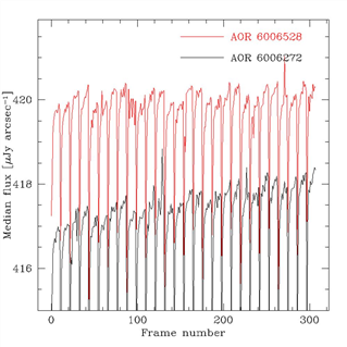
Figure 7.15 shows the median flux of each BCD (after rejection of pixels affected by cosmics and sources) for the two AORs of the ELAIS-N1 deep 24 micron observations. The background of the region observed is uniform. The observation is in photometric mode, using the offset position just to observe a more extended field. Every ten BCDs, a bias frame has been taken, which also resets the detector.
The first AOR shows a clear monotonic increasing trend. The second AOR, which has been taken a few hours later after observing a bright source, is more stable (there are however some latencies in the BCDs from this sources which have been corrected with a median stack). This effect is at the level of less than ~1%, and lasts for ~3 hr timescale. This analysis is discussed in more detail in Fadda et al. (2006, AJ, 131, 2859).
Figure 7.15: Evidence of slow response drift in two ELAIS-N1 deep 24 micron fields.
7.1.6 Bright sources and droop correction
In order to correct properly for the droop effect, one needs an accurate estimate of the total flux incident on the array. If part of the array is saturated, one doesn't know the total flux, and the part of the array that is saturated is likely to contribute significantly to the total flux. The pipeline attempts to correct for these kinds of effects as best it can, but in some cases where the array is really saturated, the droop cannot be calculated properly, resulting in a DC offset to the whole array for that frame.
If your observation includes very bright sources, you may have to manually correct that frame for this DC offset.