IRAC had no moving parts (other than the shutter, which was not operated in flightĀuntil the last 72 hours of the mission). The instrument took data by staring at the sky and sampling the arrays between resets. IRAC was capable of operating each of its four arrays independently and/or simultaneously. All four arrays were used during normal, full arrayĀoperation.
2.4.2 FowlerĀSampling
Multiple (Fowler) sampling was used to reduce the effective read noise. This mode of sampling consisted of taking N non-destructive reads immediately after the reset, and another N non-destructive reads near the end of the integration. Differencing was performed in the IRAC electronicsĀto generate one integer value per pixel per exposure to store on the spacecraft and transmit to the ground. The FowlerĀN used for an observation depended on integration time, and was selected to maximize the SNR, based on in-flightĀperformance tests.
2.4.3 Exposure Time and Frame Time
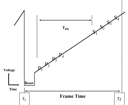
The relationship between the exposure timeĀ(Tex) and frame timeĀis shown in Figure 2.7. The exposure time is defined as the time elapsed between the first pedestal sampleĀand the first signal sample. The FowlerĀsamples were taken consecutively at 0.2-second (full array) or 0.01-second (subarray; see Section 3.1 for definitions of the full array and subarray modes) intervals in each group (pedestal and signal samples). The frame time (Tf - Ti) is the total time elapsed between resets, which could include multiple reads and dead time before and after FowlerĀsampling. The frames were commanded by specifying the number of FowlerĀsamples for the pedestal (Nf) and the number of wait ticks in between the pedestal and signal frames (Nw); then the frame time was Tf = (2Nf + Nw)τ, where τ is the readoutĀtime (0.2 seconds for full array, 0.01 seconds for subarray mode). Tex is simply Tf-Nfτ. Nf values can be found in Table 2.6. The (C)BCDĀFITS headers of the individual frames contain the information in keywords FRAMTIME (frame time), AFOWLNUM (Nf), and AWAITPER (Nwτ).
Figure 2.7: FowlerĀsampling times for one pixel (FowlerĀN=4).Ā The Pn (n=1,2,3,4) show the ōPedestalö readouts, and the Sn show the ōSignalö readouts.Ā Tex is the effective exposure time, and Tf Ā¢ TiĀ is the ōframe time,ö or total time to obtain one IRAC image.Ā The reset part of the sketch is not at the same time and voltage scale as the rest of the figure.
2.4.4 Calibration Lamps
IRAC contained two types of internal calibrationĀlamps. The first type was the flood calibrators that individually illuminated each detector. Each lamp could be controlled individually, and could be used whether the shutter was open or closed. The flood calibrators were operated at the end of each IRAC campaign in the cryogenic missionĀand used as a consistency check. The flood calibrators were not operated during the warm mission. Calibration of IRAC is discussed in detail in Chapter 4. The second type of calibration lamps was the transmission calibrator lamps, designed to illuminate all four arrays to provide an internal responsivity measurement. There were two transmission calibrator spheres, each of which contains two lamp elements. To illuminate the arrays, the shutterĀneeded to be closed, a transmission lamp turned on, and the light from the transmission lamp would reflect off a mirror on the back of the shutter. Note that because the shutter was not operated during the nominal operations except for the last 72 hours, the transmission calibrators were not used in flight.
2.4.5 Firmware
The IRAC firmware controlled the focal plane assemblies, calibrationĀelectronics, and warm electronicsĀboards. Apart from autonomous fault protection, the IRAC firmware responded only to commands sent by the Spitzer Command & Data Handling (C&DH)Ācomputer. The C&DH sent setup commands to configure the electronics, requests for each telemetry packet, and integration commands to generate images. IRAC responded to each command with an acknowledgment. In the case of a command that requested telemetry, the acknowledgment consisted of the telemetry packet, which was sent on the low-speed connection between IRAC and the C&DH. There were two types of engineering data: special engineering data, which were collected every four seconds, and housekeeping data, which were collected every 30 seconds. Special engineering data were used for onboard communication between IRAC and the C&DH, while housekeeping data were used on the ground to monitor instrument performance. A command that generated images from the arrays was acknowledged on the low-speed line, and when the frame was complete, the data-ready signal was sent on the high-speed line. The frames (together with their ancillary data) were then transferred one at a time to the C&DH. The rate of transfer was two seconds per frame, which limited the data collection rateĀto a maximum of four frames every eight seconds for IRAC observations with all four arrays.
Autonomous fault protectionĀensured that the instrument would not be damaged or a significant amount of cryogen be lost if the monitored voltages or currents entered into a red limit. Fault protection was performed by comparing the voltages sampled in the housekeeping data to the red limits that were stored in IRAC memory. For example, if a voltage in the focal plane assembly went into a red limit that persisted for three housekeeping cycles, IRAC would turn off the affected focal plane array. (The individual pixel values were not monitored, so a bright astronomical source did not trigger a red limit.) The command sequences would continue to execute; therefore, it was possible for a normal completion of an IRAC observing campaign to occur with only three of the four arrays returning data. If a second focal plane assembly had a telemetry datum go into a red limit, then IRAC would send the C&DH (via the special engineering data on the low-speed line) a request to be turned off. If a telemetry point other than one affecting a single focal plane went into a red limit, IRAC would also send the C&DH a request to be turned off.ĀĀ