Before preparing detailed FIFI-LS observations in SSPOT, please read the updated FIFI-LS section in the SOFIA Observers Handbook regarding the Observing Modes ( Sect. 5.3 ) as this will assist in understanding the explanations in this document.
Both FIFI-LS observing modes are covered in one Astronomical Observing Template (AOT) accessible from the one FIFI-LS entry in the SSPOT Observation-menu. The FIFI-LS specific parameters are distributed over three panels in SSPOT. The Config panel covers the grating configuration, i.e. the wavelength settings. The Mode panel sets the observing mode (Symmetric/Asymmetric Chop Mode) and the associated chop and nod parameters. The integration time and map parameters are set in the Map panel.
More general instrument independent, optional parameters are covered here on the FORCAST page for SSPOT. Consult the SSPOT Users Guide, which came with the application, for the general usage of SSPOT. If an altitude higher than 38,000ft was entered in the Exposure Time Estimator, select "Low" or "VeryLow" for "Requested WV Overburden" in the "Observing Condition"-panel.
The FIFI-LS Specific Panels
Config Panel - Selecting the Grating Parameters
The first parameter "Observation Order" informs the Instrument Scientist in which order the observations should be carried out. For AORs for different targets the number can be identical and the order is dictated by the observing schedule. However, for AORs with the same target an order needs to be established. If identical numbers are used for "Observation Order" on the same target, SSPOT will complain. This information helps the Instrument Scientist to prepare the observations for execution by defining the observation order.
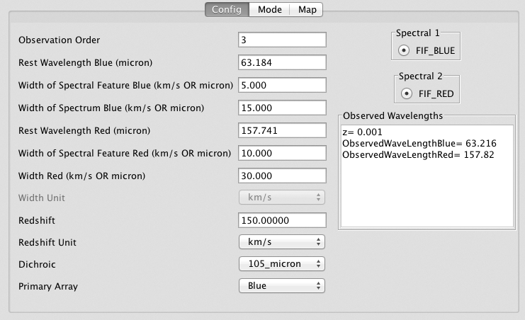
Otherwise, the Config-panel allows setting the grating configuration. Note, that the way the wavelengths are entered is different from the previous cycle . The user enters the rest wavelengths for the "blue" and the "red" transition to be observed with this AOR. For both transitions also enter the width of the spectral feature of interest and the total width of the spectrum to be observed in km/s except for the Spectral Scan mode where the unit is microns. The width of the spectral feature is only used by the Instrument Scientist together with the information in the proposal to judge, if there is enough baseline on both sides of the feature, when the observation returns a spectrum of the requested width. Thus, the value used in the execution of the AOR is the second width parameter. Both width parameters for each channel can be left at 0km/s for unresolved lines and a minimal spectral dither pattern will be executed, which will include slightly more than the bandwidth (see Sect. 5.2.1 ). If a wider spectrum is requested the grating scan will be adjusted to include the specified width (the observing wavelength will be in the center of the spectrum). In the map panel , adjust the observing time accordingly (factor ℓ in Sect. 5.2.2 ).
Enter the Doppler shift or red-shift of the source either in km/s or as a red-shift z. The "Observed Wavelengths" box reports the actual wavelengths to be observed according to the entered Doppler or red-shift.
One of the two dichroics needs to be selected so that an observation of both lines is possible ( Sect. 5.1.2 ).
For most applications, the primary array can be left at "blue". This choice will place the target coordinates (plus any mapping offsets, if applicable) on the center of the blue array. Ideally this would also be the center of the red array, but actually the red array is offset almost 10''. This offset is not reflected in the SSPOT visualizations. The target coordinates will still be relatively close to the center of the red array. Choosing the red array as primary array will put the target in the center of the red array, but relatively close to the edge of the blue array. Spectral 1 (FIF_BLUE) and Spectral 2 (FIF_RED) are fixed values.
Mode Panel - Selecting the Chop Parameters
In the mode panel shown below, the chopping mode and parameters are set.
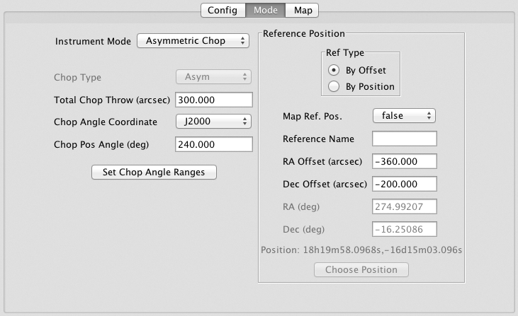
The user chooses between the Symmetric Chop, Asymmetric Chop, Bright Object, and Spectral Scan Mode (shown in screenshot) and specifies the total chop throw in arc-seconds. The position angle of the chop is specified as Chop Angle relative to the chosen coordinate system: J2000 or HORIZON. In J2000, the Chop Angle runs counter clockwise from north. The choice of HORIZON allows to chop relative to the quasi-horizontal telescope coordinate system, which can be used to chop at constant airmass (Chop angle 0). The visualization in SSPOT cannot know the corresponding position angle on the sky and plots the chop aligned with the FOV. Different position angles can be simulated by changing the FOV angle on the map panel.
If the Asymmetric Chop or Bright Object Mode is selected, a reference position is required. This can be done by specifying an offset from the target position or by specifying an absolute position (box "Ref Type"). If specifying an absolute position (Ref Type → By Position ), the "Choose Position"-button allows the user to enter sexagesimal numbers or to resolve object names. The map offsets (see the map panel ) will not be applied to the reference position unless "Map Ref. Pos." is set to "true".
The image below visualizes the asymmetric chop with only one map position. The chop and nod parameters in this example are the ones from the screen shot above. The concentric squares are the FIFI-LS FOVs. The squares with the star in it is on source. The green squares are the off-source chop separated from the target by 300" at an position angle of 240˚ (North is to the upper left corner. The grid shows equatorial coordinates.) The turquoise squares are the reference position specified as a relative offset, while the magenta squares are the off-chop for the reference position.
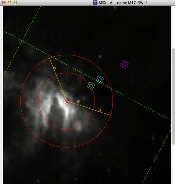
When chopping asymmetrically, the maximum chop amplitude varies with the position angle. The maximum chop throw varies between 250" and 600". The range of position angles (PAs) where the maximum chop throw is below 600" is fixed with respect to the telescope. That means that the range of PAs with a limited chop throw is limited with respect to equatorial coordinates (J2000) depends on the rotation of field during the observation or with other words, when the observations is carried out. Since that is not known while the AORs have to be prepared, you need to enter a range of possible chop angles, if the chop throw is larger than 250". Then the button "Set Chop Angle Ranges" is sensitive. Use it to open a dialog box to enter range(s) of possible chop angles. The visualization above shows a possible range from 190˚ to 320˚.
When the Spectral Scan is selected, the chop type can be chosen to be either symmetrical or asymmetrical.
Map Panel-Setting the Integration Time and Map Type
Apart from the map parameters, the integration time is set on the map panel, which is shown below.
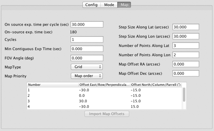
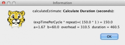
First, specify t nod , the "on-source exp. time per cycle", per nod cycle that is. Since a nod cycle must not take too long, the maximum values are 30s and 15s for the symmetric and asymmetric chopping, respectively. These values yield the best observing efficiency. To achieve longer exposure times, increase the number of nod "Cycles" to reach the desired t on , the on-source integration time per map position, as t on = cycles x t nod . This is the derived by the FIFI-LS exposure time calculator (see also Sect 5.2.2 ).
If shorter integration times are sufficient, the maximum values might still be the best option as the observing efficiency goes down with smaller values for t nod and the grating scan will get coarser (less spectral redundancy) as less time is available for it. The smallest t nod in the Symmetric Chop Mode is 20s and 10s in the asymmetric mode. For bright objects, where one chop cycle is already sufficient, i.e. t on is 10s or less, the Bright Object Mode can be used. It is more efficient, because two map positions are observed per reference position.
The overhead estimate for the Spectral Scan Mode is a rough estimate for this Shared Risk mode and will depend on the exact nature of the observation. Please contact the Instrument Scientist through the helpdesk.
The field "On-source exp. time" reports t nod times the number of map positions. Multiply this duration with the number of cycles to get the total on-source exposure time for the whole observation. Or click the "Observation Est..."-button to get the total on-source time, the overhead, and total observing time. The total duration includes a 60s overhead to setup the observation.
The "Minimum Contiguous Exp Time" field can be left at 0s unless a long observation ( >1 h) is requested that must not be split and scheduled on separate observing legs or flights. Set this value to the minimum duration required for an observing leg. See also Sect 4.1 of the Flight Planning White Paper .
The position angle of the FOV of FIFI-LS is specified via the "FOV angle" parameter (see also Sect. 5.1.3 ). If the angle is 0, the FOV is aligned so that North is up on the array. This angel rotates the FOV and any map offsets counterclockwise.
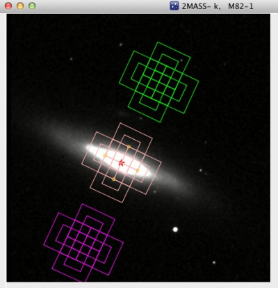
Two types of maps are supported: Grid and Custom. If "Grid" is selected, a rectangular grid of map positions can be specified, including an offset of the center of such a grid from the target position. If "Custom" is selected, the map offsets for a custom map optimized for the source geometry can be read in from a two-column csv-file containing the map offsets in arc-seconds. Make sure that there are no empty lines in the file. For both types, the offsets are specified along the FOV axes. The screen shot below shows the use of a custom map: a 5-point cross with 30" arms. The visualization below shows this map, including the -25˚ FOV rotation from the example above on top of M82 with a symmetric chop.
The parameter "Map Priority" informs the Instrument Scientists how to prioritize the map observation. If "Map Order" is selected, the order of the map positions is strictly followed as listed in SSPOT. If for unforeseen circumstances there the observing time is cut short during a flight, the last map positions might be missing, but most of the map positions will have been observed as long as planned. If "Coverage" is selected, the map is observed by looping through the map positions a few times, which ensures that the whole map is observed if, the observing time is cut short, but it will (partly) less deep than planned.
If you have any questions, please contact the SOFIA help-desk