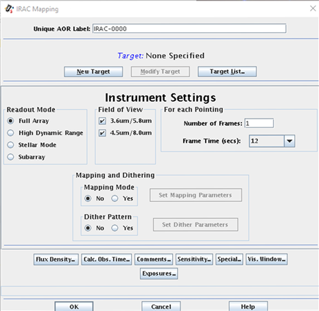
The cryogenic and warm IRAC Astronomical Observation Templates (AOTs) consisted of a (optional) dither pattern superposed on a (optional) rectangular grid raster (mapping). An example of what the template looked like is given in Figure 3.1. More examples can be found in the Observation Planning Cookbooks at IRSA’s Spitzer web pages:
Figure 3.1: IRAC AOT template. The options for selecting observing mode, fields of view, frame repeats, dithering and mapping are shown.
3.1 Readout Modes and Frame Times
There were several possible observing modes, including full array, high dynamic range (HDR), subarray, stellar, and peak-up.
During the cryogenic mission, there were four selectable full array mode frame times: 2, 12, 30, and 100 seconds (and a fifth, 200 seconds, during the early mission; see Section 2.4.3 for more information about frame times and exposure times). The warm mission added the 0.4 and 6 second frame times. To allow sensitive observations without losing dynamic range, there was a high dynamic range option. When this option was selected, the IRAC AOT took extra frames, with frame times shorter than the selected frame time. Information about the HDR frame times is given in Table 2.7. No spacecraft repositioning was done between frames, and the frames were always taken from the shortest to the longest. If dithers were selected, then the entire frame set was repeated at each dither position. If mapping was selected, then the dithers and optional HDR frame sets were repeated at each map position.
A stellar photometry mode was available for observations of objects much brighter in channels 1 and 2 than in 3 and 4 (typically stars) in the cryogenic mission. This mode took short exposures in channels 1 and 2, and long exposures in channels 3 and 4. Originally developed as an engineering mode for taking observations of the calibration stars, this mode was made available for all the observers. Three framesets were available. The shortest set took a single 0.4 second frame in channels 1 and 2, and a 2 second frame in channels 3 and 4. The next set took two undithered 2 second frames in channels 1 and 2, and a 12 second frame in channels 3 and 4. The longest frame time combination took two undithered 12 second frames in channels 1 and 2, and a 30 second frame in channels 3 and 4. The sensitivities of each frame were identical to those in the full array mode. Dithering and mapping were also available in this mode.
In the subarray mode, only one corner, a 32×32 pixel square portion of the array (a field of view of 38 arcseconds × 38 arcseconds) offset by eight pixels from the edges was read out from one array. Pixels (9:40, 9:40) in raw frame coordinates of the array were read out (thus in [C]BCD data the location is 9:40, 217:248 in channels 1 and 2). The subarray pixel size was the same as the full array pixel size (≈ 1.2 arcseconds). Fowler sampling was performed as in the full array mode, but 64 subarray images of the specified frame time were taken in succession (so the total time spent is 64 x TF) and tiled into a single 256×256 pixel image before the data were sent from IRAC. In the subarray readout mode, there were three selectable frame times: 0.02, 0.1, and 0.4 seconds in the cryogenic mission. The warm mission added the 2 second subarray frame time. This means that the durations of a single frame set of 64 subarray images at each of the four subarray frame times were 1.28, 6.4, 25.6, and 128 seconds, respectively. In the subarray mode, Fowler sampling was performed at 0.01 second intervals. The IRAC AOT moved the telescope to point at the target in the subarray region of each requested channel, in turn. For the 0.02 second frame time, data rate limitations allowed only data in the channel actually pointing at the target to be taken. For the 0.1, 0.4, and 2 second (the last frame time in warm mission only) subarray frame times, data were taken in all four (two for the warm mission) channels at each pointing position, although only one channel at a time pointed at the target.
The subarray mode was useful for observing very bright sources, obtaining high temporal resolution, and for minimizing data volumes when observing single targets. No CBCDs were generated in the pipeline for subarray data, but the pipeline produced simple stacks of 64 frames median-averaged together (*sub2d.fits). Mapping was not allowed in the subarray mode. However, small maps could be made using a cluster target. To make a mosaic of subarray data, users can use the *sub2d.fits images with corresponding uncertainty and mask files that are available with the BCD files. The *sub2d.fits images are median stacked two-dimensional combinations of the 64 plane BCD subarray cubes. These files can be used in the MOPEX mosaicking software (Makovoz & Khan 2005) in a similar way to the full array (C)BCD frames.